In the previous article of the Raspberry Pi Cat Motion Siren project, we focused on deploying .NET applications to the Raspberry Pi using GitHub Actions and Docker. Now that the deployment mechanism is established, it's time to delve deeper into the application code and Raspberry Pi hardware.
This post specifically addresses the process of connecting a passive infrared (PIR) motion sensor to the Raspberry Pi, configuring it, and reading its data from a .NET application. To familiarize yourself with the hardware utilized in this project, please refer back to the project overview.
Passive Infrared Motion Sensors
PIR motion sensors, like the HC-SR501 used in this project, operate based on the detection of changes in infrared radiation levels. They employ logical algorithms to determine the presence of motion and set the sensor's output to a high state when motion is detected. However, it's important to note that the interpretation of motion can be subjective and influenced by various factors such as the sensor's hardware settings, the surrounding environment, and the application code responsible for reading the sensor.
Here are some specific details about PIR motion sensors:
1. Initialization: Upon powering on, the sensor requires approximately one minute to acclimate to the current infrared levels. This initialization period allows the sensor to establish a baseline for future comparisons.
2. Pyroelectric Sensors: PIR sensors utilize a Fresnel lens that focuses infrared (IR) signals onto two distinct pyroelectric sensors. These sensors handle positive and negative outputs.
3. Triggering Motion: When the IR levels detected by the pyroelectric sensors differ, the PIR output is triggered, indicating the presence of motion.
4. Differential Amplifier: A differential amplifier is incorporated to cancel out signals when both sensors detect the same change simultaneously. This helps reduce false positives caused by brief flashes of light or other interferences that might not actually indicate motion.
These details highlight the functioning and features of PIR motion sensors, shedding light on how they detect and respond to motion in their surroundings.
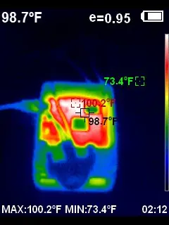
Infrared Imagery
For a hands-on experience with infrared technology and to enjoy some excitement, a thermal imager can be employed. While there are more affordable options available, such as the FLIR One module that can be attached to a phone, it's important to note that high-quality thermal imaging devices can be quite expensive. For instance, I purchased and subsequently returned the HTI HT-18 Thermal Imaging Camera, which costs over $400 and offers only a modest “prosumer” level of quality. While I personally didn't have a strong enough requirement to retain it, a thermal imager can be a valuable tool for various purposes, including home inspections (such as assessing electrical systems, plumbing, insulation around windows) as well as automotive applications, among others.
Hardware
Electrical Disclaimer
Before delving into the hardware and wiring aspects, I want to emphasize that I am not an electrical engineer, hardware specialist, or an expert in Raspberry Pi electronics. It is always crucial to consult the documentation provided by the hardware manufacturer and seek guidance from experts in the field.
On the topic of documentation, it's worth mentioning that some kits purchased from China may have documentation with subpar English. In some cases, there might be inconsistencies or conflicting information between the documentation and online sources. To avoid potential damage to components, injuries, or frustration, it is advisable to cross-reference information from multiple sources. By doing so, you can ensure a more reliable understanding and implementation of the hardware setup.
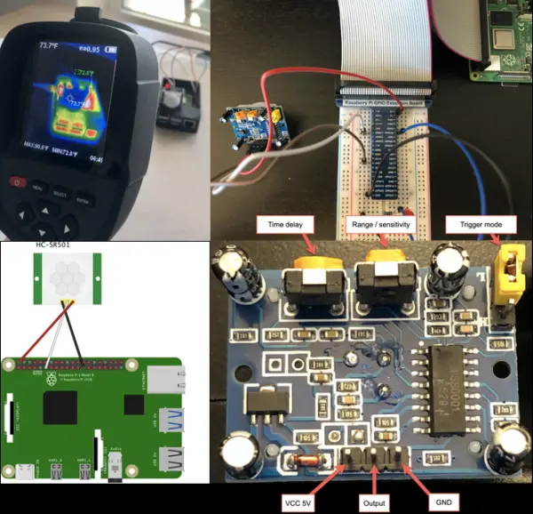
HC-SR501 PIR Motion Sensor
The image provided below showcases my HC-SR501 PIR sensor, accompanied by added call-outs for reference. It's important to note that there may be slight variations among different versions of the sensor.
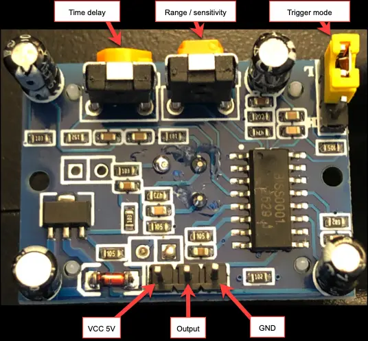
Let's start with the connections located at the bottom of the HC-SR501 PIR sensor. The leftmost connection is used for power/input voltage (ranging from 5V to 20V DC). In the middle, we have the output connection. When motion is detected, the output will be high (3.3V), and when there is no motion, it will be low (0V). On the right side, we have the ground input.
Moving to the top of the sensor, there are several adjustable settings. Starting from the left, there are two potentiometers and a jumper on the far right.
1. Time Delay: This setting determines how long the sensor will remain in a high/on/hot state after detecting motion. Rotating the potentiometer counterclockwise to the left sets the time delay to around 3 seconds, while turning it clockwise to the right increases it up to 5 minutes.
2. Sensitivity/Range: This setting controls the detection range of the sensor. Adjusting the potentiometer to the full left provides a range of 7 meters, while moving it to the full right reduces the range to 3 meters. The sensor's detection area spans a 110-degree arc from its center.
3. Trigger Mode Selection: The jumper on the far right determines the trigger mode of the sensor. In the pictured configuration, it is set to single trigger mode. This means that as soon as motion is detected, the countdown to the time delay begins. Alternatively, moving the jumper cap to the bottom pins enables repeatable trigger mode. In this mode, the countdown to the time delay will reset as long as motion continues to be detected.
These settings can have an impact on the code that reads the sensor, so it's important to consider them beforehand. In this case, the time delay was set to 3 seconds for a more real-time reading, with the option to introduce delays in the code if necessary. The sensitivity/range was left at its default mid-point setting, but adjustments may be made later based on the Raspberry Pi's location and requirements.
Initially, I set the trigger mode to “single” on the PIR sensor. However, I later decided to change it to “repeatable.” In single trigger mode, there is a 3-second period after the time delay expires where the sensor remains inactive and reports no motion (reading low/off). This could lead to frequent “blind” periods and interruptions in motion detection. On the other hand, repeatable trigger mode resets the timer whenever there is a variance in infrared levels, providing a more accurate and smoother experience. With repeatable mode, the sensor avoids frequent on/off switching and maintains better continuity in motion detection.
Quick Breadboard Test
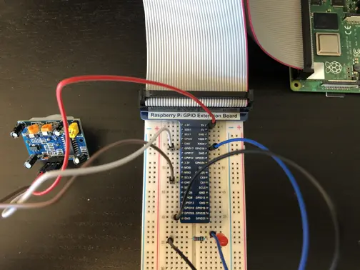
Initially, I began the setup without using a breadboard, as it required fewer wires to connect the motion sensor directly to the Raspberry Pi. However, I soon realized the benefits of using a breadboard for quick tests and experiments. Additionally, following the tradition, it is customary to start with a blinking LED, which serves as a useful indicator for the state of the PIR sensor.
Below is my initial attempt at creating a breadboard diagram using Fritzing. You can find the .fzz files in the project documentation. For this setup, you will need the following components: 3 male/female jumper cables for connecting the PIR sensor, 1 LED, a 220 Ω resistor (which can be trimmed down) to limit the current drawn by the LED, and 2 male/male cables – one for connecting the LED to the Pi and the other for grounding the resistor.
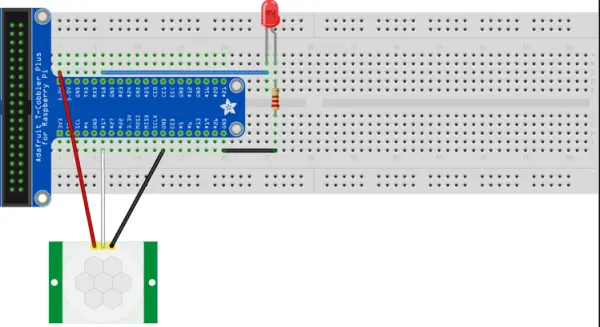
During my research, I encountered conflicting information in the documentation regarding the appropriate power supply voltage for the PIR sensor. While technically it worked with a 3.3V power supply, opting for a 5V power supply was the safer choice.
It could be beneficial to review fundamental concepts related to Raspberry Pi wiring, breadboards, LEDs, and resistors. Depending on the power requirements, the number of LEDs used, and other factors, it might be necessary to use a resistor with a different resistance value. Exploring similar examples or performing calculations can provide further clarity and ensure the correct resistor selection for your specific setup.
The code provided below is a basic test to quickly verify the functionality of this setup. However, please note that this code does not consider the time it takes for the sensor to acclimate after being powered on. It may take a minute or more for the sensor to provide accurate readings.
using System;using System.Device.Gpio;using System.Threading;namespace MotionSensorTest{ class Program { private const int PIR_PIN = 17; private const int LED_PIN = 18; static void Main(string[] args) { Console.WriteLine("Initializing GPIO"); using (var gpio = new GpioController()) using (var cts = new CancellationTokenSource()) { Console.CancelKeyPress += (s, e) => cts.Cancel(); gpio.OpenPin(PIR_PIN, PinMode.Input); gpio.OpenPin(LED_PIN, PinMode.Output); Console.WriteLine("Monitoring PIR sensor. ctrl+c to cancel."); bool lastOn = false; while (!cts.IsCancellationRequested) { bool pirOn = gpio.Read(PIR_PIN) == true; if (lastOn != pirOn) { Console.WriteLine($"Motion sensor is now {(pirOn ? "on" : "off")}"); lastOn = pirOn; gpio.Write(LED_PIN, pirOn); } } Console.WriteLine("Cleaning up"); gpio.ClosePin(PIR_PIN); gpio.ClosePin(LED_PIN); } } }}While the breadboard setup is in place, it is an opportune moment to shut down the Raspberry Pi, experiment with different PIR sensor hardware settings, power it back on, and conduct additional tests to observe the impact of these changes. This allows for the evaluation of how different sensor configurations affect the functionality and behavior of the system.
Pi Motion Sensor Wiring
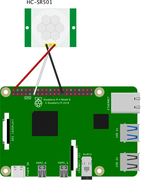
Using the PIR sensor without a breadboard is a simple process requiring three female-to-female jumper cables.
1. Connect the power pin of the PIR sensor to the 5V power pin of the Raspberry Pi.
2. Connect the output pin of the PIR sensor to the BCM 17 pin (physical pin 11) of the Raspberry Pi.
3. Connect the ground pin of the PIR sensor to any ground pin on the Raspberry Pi.
By establishing these connections, you can effectively integrate the PIR sensor with the Raspberry Pi, allowing for motion detection and data reading.