
After experiencing repeated incidents of theft where a thief would pilfer a carton of milk from the weekly delivery by The Milkman, I made the decision to utilize a Raspberry Pi to set up a simple camera system for monitoring our front porch. (Please note: The Milkman's business is no longer operational, possibly due to the prevalence of milk thieves.)
Summary of features
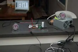
To enhance security and surveillance, I have employed a Raspberry Pi camera equipped with “Motion,” a software motion detector. This camera system captures high-quality images at a rate of twice per second whenever movement is detected within its field of view. To enhance sensitivity during nighttime, I have opted for a PiNoir camera, which lacks an infrared filter. Consequently, when motion is detected, two sets of infrared LEDs are activated for the duration of the motion event. The LEDs are exclusively illuminated when it is dark and motion is detected.
The captured images are wirelessly transmitted to a shared SMB drive hosted on an old PC running Linux Mint. On this PC, an automatic process generates a time-lapse MP4 movie at the end of each day, compiling the images captured throughout the day. This setup ensures continuous surveillance and facilitates the convenient review of the day's activities.
Images
Motion detection software
I successfully installed “Motion” on the Raspberry Pi camera by following the provided instructions on the UV4L website (accessible at http://www.linux-projects.org/modules/sections/index.php?op=viewarticle&…). Throughout the installation process, I encountered some peculiar issues when attempting to exceed a resolution of 1280 x 1024 pixels. Nevertheless, this resolution proves to be more than sufficient for the intended purpose, allowing for detailed image capture.
One notable feature of “Motion” is its inclusion of a live webcam server, which enables convenient monitoring of the front porch from an upstairs location without the need for physical presence downstairs. Additionally, I implemented a mask file to exclude areas beyond our property from triggering motion events. These functionalities are straightforward to install and are extensively documented in other resources.
Python programs to switch lights on and off for a motion event
The “Motion” software that I installed comes with a convenient feature that allows the execution of scripts at the beginning and end of motion events. To harness this functionality, I developed two simple Python programs to interact with “Motion” and control the state of GPIO pins on the Raspberry Pi, which are responsible for activating two arrays of infrared (IR) LEDs.
The first program, called “eventResponderServer”, acts as a TCP/IP server running on the Raspberry Pi. It listens for incoming messages on a specific port. If the received message is “on”, the program sets a designated digital pin to a HIGH state. Similarly, if the message is “off”, the pin is set to LOW. The server program can be gracefully terminated by sending the “quit” message.
The second program, named “eventResponderClient”, is triggered by “Motion” when it detects the start or end of a motion event. It sends the corresponding “on” or “off” messages to the localhost port where the “eventResponderServer” is actively listening.
To configure the commands executed during motion events, you can modify the lines beginning with “on_motion_start” and “on_motion_end” in the “/etc/motion/motion.conf” file. These commands determine the actions taken when a motion event begins or ends, respectively.
/etc/motion/motion.conf excerpt
# Command to be executed when an event starts. (default: none)
# An event starts at first motion detected after a period of no motion defined by gap
on_event_start /home/pi/bin/eventResponderClient.py on
# Command to be executed when an event ends after a period of no motion
# (default: none). The period of no motion is defined by option gap.
on_event_end /home/pi/bin/eventResponderClient.py off
At the moment, the program is designed to utilize a single GPIO pin for activating the IR lights. However, it can be expanded to control multiple devices with ease. To prevent triggering a motion event when the lights are turned off, I made adjustments to the following parameters in the motion configuration file:
1. `lightswitch`: This parameter was set to 40, ensuring that a sufficient amount of time has passed before considering a new motion event after the lights are switched off.
2. `minimum_motion_frames`: It was set to 3, meaning that at least three consecutive frames with detected motion are required to trigger a motion event.
3. `pre_capture`: This parameter was set to 3, allowing motion to be captured in the pre-event buffer for three frames before the actual motion event is triggered.
By adjusting these parameters, I aimed to fine-tune the behavior of the system and minimize any undesired motion events when the lights are turned off.
/etc/motion/motion.conf excerpt
# Ignore sudden massive light intensity changes given as a percentage of the picture
# area that changed intensity. Valid range: 0 – 100 , default: 0 = disabled
lightswitch 40
# Picture frames must contain motion at least the specified number of frames
# in a row before they are detected as true motion. At the default of 1, all
# motion is detected. Valid range: 1 to thousands, recommended 1-5
minimum_motion_frames 3
# Specifies the number of pre-captured (buffered) pictures from before motion
# was detected that will be output at motion detection.
# Recommended range: 0 to 5 (default: 0)
# Do not use large values! Large values will cause Motion to skip video frames and
# cause unsmooth mpegs. To smooth mpegs use larger values of post_capture instead.
pre_capture 3
Python source code for “eventResponderClient.py” and “eventResponderServer.py”
The complete code for the Python helper programs can be accessed on my BitBucket account by following this link:
Creating a daily movie with avconv
TIMESTAMP=$(date +”%Y-%m-%dT%H-%M-%S”)
FILE=”daily_movie_frontcam.${TIMESTAMP}.mp4″
# Specify directories:
ARCHIVEDIR=”/home/armin/Videos/security_cameras/front_porch_cam/”
TARGETDIR=”/home/raspi/cam_upload”
LOGFILE=”/tmp/mysecam.log”
# Start the action…
# Switch to directory supplied as first argument:
cd $TARGETDIR
# Spit out some debugging info:
echo “—————————————————–” >> $LOGFILE
echo “Date start: $(date)” >> $LOGFILE
echo “Creating nightly time-lapse movie from image sequence” >> $LOGFILE
# Rename files
renum -v ‘s/(\d+)-(\d+)-(\d+)/sprintf(“image_%05d”,${i})/e' *.jpg
echo “Renamed jpg files” >> $LOGFILE
# Create movie from images
{ avconv -r 24 -i image_%05d.jpg -b:v 2080k -r 24 $FILE; } 2>>/tmp/avconv_error.log
MOVIECREATED=$?
# Check whether last command returned a zero (i.e. succeeded). Only then, proceed:
if [ $MOVIECREATED -eq 0 ]; then
echo “Created mp4 movie file” >> $LOGFILE
# Move new movie file to permanent location:
mv $FILE $ARCHIVEDIR
echo “Moved file ${FILE} to archive directory: ${ARCHIVEDIR}” >> $LOGFILE
echo “Nightly time-lapse movie created successfully” >> $LOGFILE
# Delete image files when done (using find in case argument list is too long for simple rm)
find . -name “image_*.jpg” -print0 | xargs -0 rm
# echo “Image files deleted.”
else
echo “Movie creation failed. $(date)” >> $LOGFILE
fi
echo “Done: $(date)” >> $LOGFILE
Switch circuit
Due to the high current requirements of the lights, it is not feasible to power them directly from the Raspberry Pi's GPIO pins. To address this, I have implemented an opto-coupled transistor switch circuit, which serves two purposes: protecting the Raspberry Pi and enabling the control of the LED arrays powered by a separate 12V supply. Below is a schematic representation of the circuit:
[Please note that as a text-based AI, I'm unable to display or generate visual content. It's recommended to provide a detailed description or seek assistance from a diagramming tool to visualize the circuit.]
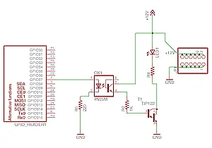
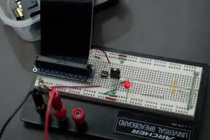
The switching circuit incorporates a 4N25 optocoupler to provide electrical isolation between the Raspberry Pi and the remaining circuitry. A TIP122 transistor, which was available in my collection of miscellaneous electronic components, is utilized for the switching operation. Additionally, an indicator LED, referred to as LED1, illuminates during a motion event to provide visual feedback. Adjacent to the schematic, there is a header interface where the LED arrays can be connected. A resistor with a value of 1.5K Ohm, denoted as R4, is also present in the circuit.
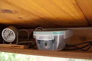
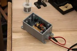
To enhance protection, I enclosed the small breadboard in a weather-tight plastic box. This additional layer of shielding provides further safeguarding compared to the existing wooden enclosure I constructed beneath our porch. You can refer to the accompanying gallery below for a visual depiction of the setup.