
Project Idea
Let me transport you back in time, precisely six years ago, when my 12-year-old son was merely six years old. Ah, the joys of being six!
At that age, six-year-olds possess a peculiar sleep schedule. They tend to sleep in on school days, almost missing the bus each morning. However, come Saturdays, they miraculously wake up an hour earlier than necessary, eagerly seeking out their favorite cartoons.
Understanding the concept of time is still a bit fuzzy for six-year-olds. You can't simply tell them, “Stay in bed until 7:30 am.” And even if you did, they wouldn't comply. So, how can you assist kids in learning to stay in bed until 7:30 am on a Saturday morning? Well, we turned it into a game!
Coincidentally, my son had just received a Raspberry Pi from his grandfather, along with the challenge of using it to create a project. Perfect timing! We had the Raspberry Pi, and now we had a purpose for it. Could we utilize the Raspberry Pi to help him determine if it was too early to rise? Kids grasp the concept of red meaning stop and green meaning go from an early age. So, we came up with an idea to construct a traffic light using the Raspberry Pi. By pushing a button, the Pi would check the day and time. If it was past 7:30 am on a Saturday, the light would turn green, signaling it was acceptable to get out of bed. However, if it was before 7:30 am, the light would turn red, indicating it was time to stay in bed. We soon realized this concept could also be applied at night. After 8 pm? Red light—stay in bed. Before 8 pm? Green light—more playtime!
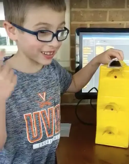
With this exciting project in mind, my son and I embarked on the journey of constructing a traffic light using cardboard, a button, and three LEDs. The image above showcases our homemade traffic light creation, which brought us both joy and a valuable learning experience.
The Build
Parts List:
- Raspberry Pi
- wires
- Red, Green, Yellow LED
- tape
- yellow spray paint
- breadboard
- button
For our traffic light project, we utilized basic materials such as cardboard, tape, and yellow spray paint to bring it to life. The traffic light itself was constructed using these materials, creating a sturdy structure. To add functionality, we incorporated red, yellow, and green LEDs, which illuminated the light in a captivating manner.
At the top of the traffic light, we positioned a small push button. This button served as the control mechanism, allowing us to activate the system and display the appropriate light based on the time. Acting as the brains of the unit, we employed a Raspberry Pi, which handled the logic and operations. To establish the necessary connections, we used wires and a breadboard, ensuring everything worked seamlessly together.
This combination of simple materials, electronic components, and the Raspberry Pi enabled us to bring our traffic light project to fruition, creating a visually appealing and interactive system.
Wiring Diagram
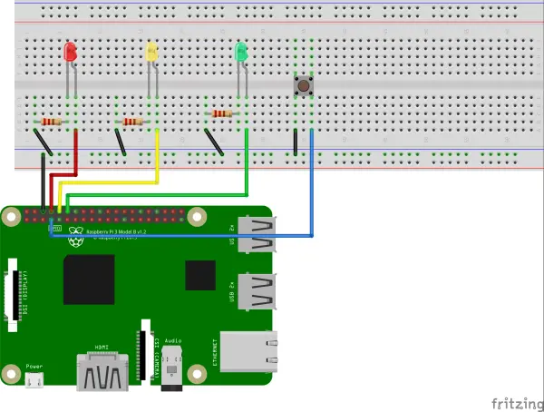
To establish the connection between the Raspberry Pi and the three LEDs, we followed a specific wiring configuration:
- The red LED was connected to pin 18 of the Raspberry Pi, with a 100 ohm resistor placed between the LED and the ground.
- The yellow LED was connected to pin 14 of the Raspberry Pi, with a 100 ohm resistor connected in series between the LED and the ground.
- The green LED was connected to pin 15 of the Raspberry Pi, and like the others, a 100 ohm resistor was placed between the LED and the ground.
Additionally, we connected the push button to pin 4 of the Raspberry Pi, creating the necessary input for controlling the traffic light system. The other terminal of the button was connected to the ground.
By adhering to this wiring setup, we established the essential connections between the Raspberry Pi, the LEDs, and the push button, enabling the system to function as intended.
Test Code
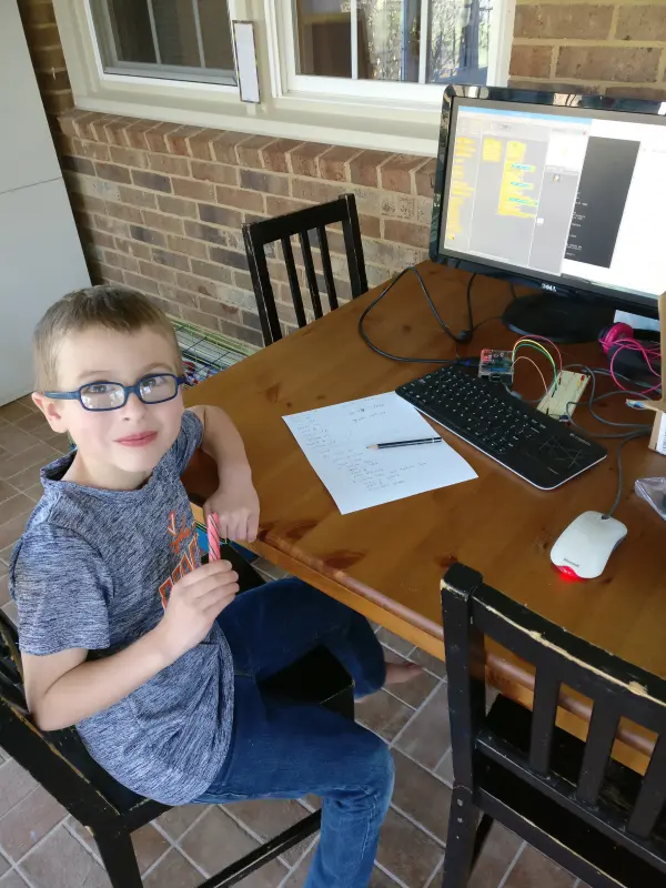
One of the remarkable aspects of this project was the involvement of my 7-year-old, who took the initiative to design and code the traffic light (with a little assistance). We began by jotting down the desired logic and sequence of the traffic light on a piece of paper. With a few instructions and guidance, he was able to leverage Scratch, a visual programming language available on the Raspberry Pi, to bring his code to life.
Using Scratch, he was able to utilize its user-friendly interface and drag-and-drop blocks to construct the code for the traffic light. With each block strategically placed, he defined the sequence of the lights and the corresponding timings. It was an incredible learning experience for him as he grasped the fundamental concepts of coding while working on this project.
With a bit of guidance and encouragement, my 7-year-old successfully transformed his ideas into a functional code using Scratch on the Raspberry Pi. It was an exciting and empowering moment for both of us as we witnessed the power of hands-on learning and creativity in action.
The code for this project was created using Scratch, a graphical programming software that employs color-coded blocks to represent different coding structures. Scratch offers a visually intuitive approach to coding, making it easy to identify which parts of the code belong to specific control structures. For instance, it becomes clear that a particular section of the code functions within an ‘if' statement.
Below is the code for a simple traffic signal with a ‘walk' button, providing the foundation for my son's traffic light project:
Using Scratch, we were able to assemble this code, which forms the basis of the traffic signal and incorporates a ‘walk' button functionality. It demonstrates the sequential activation of the lights with specific timing intervals. This code provided a starting point for my son's project and allowed him to understand the fundamental concepts of programming in an engaging and visual manner.
Here’s the code explained:
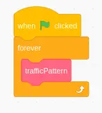
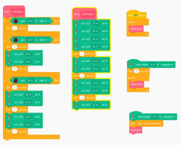
The code block featuring the green flag in Scratch serves as the starting point for the program. When the green flag is clicked, the code within this block is triggered and the program begins executing. It initiates the traffic pattern code, dictating the behavior of the traffic lights.
In essence, clicking the green flag in Scratch simulates running the program, and it acts as the entry point for the traffic light functionality.
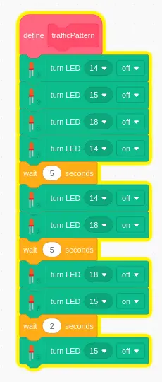
In the provided code sequence, the initial step is to turn off all the LEDs and turn on the yellow LED simultaneously. Following a pause of 5 seconds, the yellow LED is turned off, and the red LED is activated. Another 5-second pause occurs before the red LED is turned off, and the green LED is illuminated for a duration of 2 seconds. Finally, the green LED is turned off, preparing for the continuation of the code in the subsequent code block.
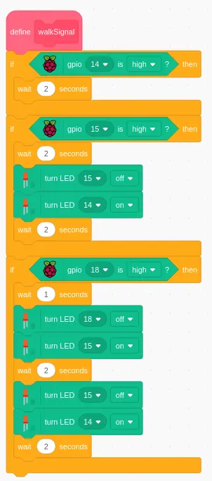
The walk signal code comprises three conditional statements using the “if” condition. Each statement checks the state of a specific LED:
- If the yellow LED (pin 14) is on when the button is pressed, it remains illuminated for an additional 2 seconds before the traffic pattern resumes.
- If the green LED (pin 15) is on when the button is pressed, there is a 2-second delay before turning off the green LED and simultaneously activating the yellow LED. After a further 2-second pause with the yellow LED on, the traffic pattern function resumes.
- If the red LED (pin 18) is on when the button is pressed, there is a 1-second delay before turning off the red LED and turning on the green LED. Following a 2-second period with the green LED on, both the green and yellow LEDs are turned on simultaneously and kept on for an additional 2 seconds.
Upon reflection, it seems questionable why the green light turns on after the button is pressed and the red LED is already on. It may be more appropriate for the red LED to remain illuminated for a longer duration.
Python Code
Although the Scratch code worked for testing purposes, additional steps were necessary to make it work in a real-life scenario. One limitation was that Scratch did not provide a way to check the current computer time. To overcome this, another programming language was required, and Python came to the rescue!
Below is the Python code that was used for the actual implementation, along with an accompanying explanation.
from gpiozero import LED
from gpiozero import Button
from gpiozero import TrafficLights
import time

# TrafficLights(red, amber, green)
lights = TrafficLights(25, 8, 7)
button = Button(21)


def traffic(hour):
  t = time.localtime()
  h = t.tm_hour
  lights.amber.on()
  time.sleep(2)
  lights.amber.off()
  if (21 > h and 6 < h):
    lights.green.on()
    time.sleep(5)
    lights.green.off()
  else:
    lights.red.on()
    time.sleep(5)
    lights.red.off()

def wakey(hour, min):
  cnt = 0
  while cnt < 10:
    if (hour == 6 and min == 40):
      lights.green.on()
      lights.red.on()
      lights.amber.on()
      time.sleep(1)
      lights.green.off()
      lights.red.off()
      lights.amber.off()
      time.sleep(1)
    cnt+=1

while True:
  w = time.localtime()
  wakey(w.tm_hour, w.tm_min)
  button.when_pressed = traffic
Code explanation
Here I will try to reinterpret the code I wrote over 6 years ago…
from gpiozero import LED
from gpiozero import Button
from gpiozero import TrafficLights
import time

# TrafficLights(red, amber, green)
lights = TrafficLights(25, 8, 7)
button = Button(21)
The initial 4 lines of code import the necessary libraries for enabling communication between Python and the Raspberry Pi. Conveniently, the GPIOZero library already provides a traffic lights module, so we can utilize that.
Lines 7 and 8 are responsible for setting up the LEDs and buttons, assigning specific pin numbers to each color LED, thus establishing their association.
def traffic(hour):
  t = time.localtime()
  h = t.tm_hour
  lights.amber.on()
  time.sleep(2)
  lights.amber.off()
  if (21 > h and 6 < h):
    lights.green.on()
    time.sleep(5)
    lights.green.off()
  else:
    lights.red.on()
    time.sleep(5)
    lights.red.off()
This function retrieves the current time, briefly flashes the yellow light for two seconds as a visual indicator, and then proceeds to check if the current hour falls between 6am and 9pm. If it does, the green light is turned on for 5 seconds. If not, the red light is turned on for 5 seconds.
def wakey(hour, min):
  cnt = 0
  while cnt < 10:
    if (hour == 6 and min == 40):
      lights.green.on()
      lights.red.on()
      lights.amber.on()
      time.sleep(1)
      lights.green.off()
      lights.red.off()
      lights.amber.off()
      time.sleep(1)
    cnt+=1
This additional function serves as an alarm clock feature. It is designed to simulate an alarm by flashing all the lights for a duration of 10 seconds. This can be used to wake up the boy at 6:40am to get ready for school.
while True:
  w = time.localtime()
  wakey(w.tm_hour, w.tm_min)
  button.when_pressed = traffic
In conclusion, here's the code that brings everything into motion. The program utilizes a perpetual while loop, as the condition “True” is inherently true. Within this loop, it fetches the current time, executes the “wakey” function, and checks for any button presses. If a button press is detected, the program proceeds to execute the “traffic” function.