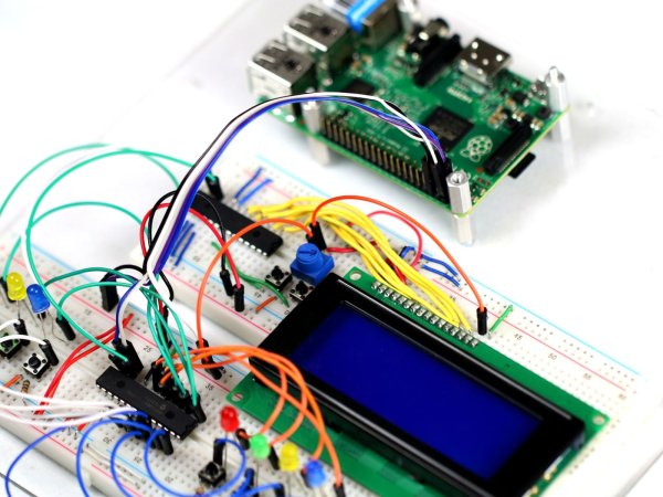
SmartFaire on Raspberry Pi 2

The SmartFaire is a project that uses the I2C bus on a Raspberry Pi 2, and two I/O port expanders to create an interactive game for the user. The game is called ā€œSpeedā€, where the user has to push all the lit buttons, simultaneously, as fast as possible. The goal is to push as many buttons as possible in 20 seconds. The user can choose to play the single player mode or the two player mode.SmartFaire on Raspberry Pi 2

Hardware

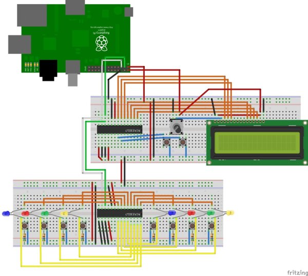
Refer to the schematic and the pin-out diagrams for the hardware connections
  • Start with all the items in the components list below.
  • Connect all the power rails (red rails) of the 2 breadboards together and all the ground railsĀ  (blue or black rails)Ā together.
  • Connect an MCP23017 port expander and the LCD Screen on the first breadboard as shown in the hardware diagram.
  • On the MCP23017Ā (see pinout diagram), pins 9, 15 and 18 go to power while pins 10, 16 and 17Ā go to ground.
  • On the LCD screen (see pinout diagram), pinsĀ 1 and 16 go to ground.
  • Pins 11 to 14 of the LCD screen connect to pins 5 to 2 of the MCP23017, and pins 4 to 6 of the LCD screen connect to pins 8 to 6 of the MCP23017, as shown in the hardware diagram.
  • Next connect the potentiometer with pin 1 to ground and pin 3 to pin 2 on the Raspberry PiĀ  (see pinout diagram).
  • Connect pin 2 of the potentiometer to pin 3 of the LCD screen, and pin 3 of the potentiometer to both pins 2 and 15 of the LCD screen.
  • Now connect 2 pushbuttons with one end to ground and the other to pinsĀ  21 and 22 on the MCP23017.
  • On the 2nd breadboard, connect the 2nd MCP23017 with pins 9 and 18 to power and pins 10, 15, 16 and 17 to ground.
  • Connect 2 sets of 4 LEDs and 4 pushbuttons as shown in the hardware diagram.
  • All the cathodes of the LEDs (shorter leg) connect to ground with a 560Ī© resistorĀ and one end of each pushbutton connects to ground with a jumper wire.SmartFaire on Raspberry Pi 2 schematic
  • On one set, the anode of the LEDs (longer leg) connect to pins 1 to 4 on the MCP23017 and the respective pushbuttons connect to pins 25 to 28 on the MCP23017.
  • On the 2nd set, the anode of the LEDs connect to pins 5 to 8 on the MCP23017 andĀ the respective pushbuttons connect to pins 21 to 24 on the MCP23017.
  • Connect pins 12 and 13 of the 1st MCP23017 to pins 12 and 13 of the second one, then connect the pin 12 to pin 3 of the Raspberry Pi and the pin 13 to pin 5 of the Raspberry Pi.
  • Finally, connect pin 1 of the Raspberry Pi to the power rail of the breadboards and pin 6 to the ground rails.
  • Your set up is now complete! Cross check it with the hardware diagram to ensure all the connections are in place.

Sofware

Confirm that your Raspberry Pi 2 is set up according to the steps here.
Once the Pi is setup, download the code from the link below and deploy it to the Pi.


Source: SmartFaire on Raspberry Pi 2

About The Author

Ibrar Ayyub

I am an experienced technical writer holding a Master's degree in computer science from BZU Multan, Pakistan University. With a background spanning various industries, particularly in home automation and engineering, I have honed my skills in crafting clear and concise content. Proficient in leveraging infographics and diagrams, I strive to simplify complex concepts for readers. My strength lies in thorough research and presenting information in a structured and logical format.

Follow Us:
LinkedinTwitter

Leave a Comment

Your email address will not be published. Required fields are marked *

Scroll to Top