
We add to Raspberry Pi a TFT touch screen to display the system console, movies and favorite photos or control a relay board … at your fingertips, literally!
To avoid using an HDMI monitor the cost well above that of Raspberry Pi, in previous articles we have always gone the way of connecting remotely to the microcomputer, using tools such as Putty and WinSCP. This approach has always bound to use Raspberry Pi in a “server” mode. Therefore we have always presented applications with user interface built to be accessible by web browser. What to do when we want to have an interface in traditional style, accessible directly from the desktop? Simple, you connect a monitor, a keyboard, a mouse and then you can code a standard desktop application using the classical languages and libraries for creating graphical user interfaces. Yeah, but this way we transform Raspberry Pi in a PC with all devices attached, making it a traditional “cumbersome” uncomfortable device.
The solution we introduce instead of the “classical”, allows you to create graphical user interfaces using a nice 2.8-inch TFT color monitor with a touch resistive interface. No monitor, no keyboard and no mouse. The display board has more or less the same Raspberry Pi size, is already assembled and is compatible with all Raspberry Pi versions: A, B and B +. In this post we have adopted the model B + that provides a greater number of I / O pins than previous versions. The monitor has a resolution of 320 x 240 pixels with 16 bits color depth. The mini display is connected to Raspberry Pi through its SPI bus and can be used to redirect the console, or as a monitor to display the Raspbian X desktop, photos, video and user applications graphical interfaces. So far, so good. The downside is that the drivers are not included in Raspbian kernel.
This cute display allows us to introduce, in more detail than we have done up to now, the build of an embedded GNU / Linux system. In the “professional” field, embedded GNU / Linux distribution are the leanest possible, including only device drivers and essential applications to the basic microcontroller operation. This is to minimize the distribution memory footprint and maximize the target system performance. This approach allows the use of a reduced performance chip, with final solution physical dimensions as low as possible and minimum power consumption in order to allow battery operated solutions.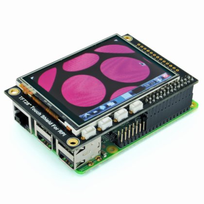 The downside is that you must customize the distribution kernel with the device drivers that you want to use, such as WiFi dongle, USB devices, LCD and LED panels. One of the advantages using Raspberry Pi has always been the ease of use, not having to deal with these issues. Being an “educational” microcomputer, Raspbian already includes a huge amount of drivers that meet automatically (plug and play) the most needs. This time, however, the TFT LCD drivers are not included. Fortunately, Adafruit (display producer) has provided a Raspian kernel, already compiled, that includes the required driver.
This avoid us having to customize Raspbian. We are still planning to propose a series of posts about the topic, because the continuous presence of new devices on the market requires fronting this issue definitely. In the Adafruit solution, there are in fact two problems. What to do when we have to connect a second device whose specific drivers are not included on the Linux kernel? Although the manufacturer makes available a “compiled” kernel for its device, we will lose other drivers integrations. The only solution is that we must configure and compile the kernel by our own, adding all the drivers requested. Second problem. Using the precompiled kernel, customized with the addition of a specific driver, it binds us to the kernel version used for compilation. In this condition, we will not be able to adopt new distributions with most recent kernels, unless the device manufacturer itself does not release a new version.
In this regard we remind that has just been released the 3.16 Linux kernel version, which has considerable additional functionality when it relates to ARM chip management with CPU and its graphics processors. A sign that we will see an increasing spread of our “philosophy”.
But back to our graphic display based on TFT LCD module ILI9340, which comes pre-assembled and equipped with GPIO connector, present on all Raspberry Pi models: A, B and B +. The board includes the display controller STMPE610 communicating with Raspberry Pi through the SPI bus and then engages the corresponding GPIO connector pin (SCK, MOSI, MISO, CE0, CE1) in addition to GPIO25 and GPIO24 pins. The four additional buttons present on board are connected to pins GPIO23, GPIO22, GPIO21, and GPIO18. All other pins are unused and may be used for other needs. In this case it is appropriate to solder a connector on housing present on the right side of the card and use a flat cable extension. Be careful to follow the right pin matching. The GPIO pin number 1 is signed on the back of the board with a square shape and a small white arrow silkscreened.
How to customize Raspbian
The process we describe to set up the TFT LCD requires starting from Raspbian. We used the image released on 9 September 2014–kernel release 3.12 .
Now it is better not to install the display on the connector, we will do it after you install the software. To perform the installation process it is necessary that Raspberry Pi is connected to the local network so you can “see” Internet. You also need to access to Raspberry Pi to use a terminal window and a file manager. As always, but especially in this case, we prefer to remotely access via SSH using (in Windows) Putty and WinSCP. Of course, you can also connect to the console via serial cable.
We login to Raspberry Pi with the user “root” and start the installation process with the usual commands to update the distribution:
apt-get update
apt-get upgrade
We go to a temporary folder to download the installation files. We can also create a specific folder for this process. The files are available as .deb packages which must then be installed with dpkg. We can use, for example, the “home” folder. We go there with the command:
cd /home
Now we download all the necessary packages to upgrade the kernel for the display management.
wget http://adafruit-download.s3.amazonaws.com/libraspberrypi-bin-adafruit.deb
wget http://adafruit-download.s3.amazonaws.com/libraspberrypi-dev-adafruit.deb
wget http://adafruit-download.s3.amazonaws.com/libraspberrypi-doc-adafruit.deb
wget http://adafruit-download.s3.amazonaws.com/libraspberrypi0-adafruit.deb
wget http://adafruit-download.s3.amazonaws.com/raspberrypi-bootloader-adafruit-20140917-1.deb
After the download, from the same folder, install everything with the command:
sudo dpkg -i -B *.deb
This takes quite a long time, you can take a break and relax for a moment. If you are using an old Raspbian (prior than September 2013), you must disable the use of the accelerated framebuffer X, with the command that removes the configuration file of the accelerator and saves it to the folder / home (you never know):
mv /usr/share/X11/xorg.conf.d/99-fbturbo.conf /home
Now we turn off Raspberry Pi with the traditional command:
shutdown –h now
We remove the power plug; insert the display on the GPIO connector, making sure that there is no false contact with any other Raspberry Pi connector or component and then we power on. Do not worry, on the small screen, for the moment, nothing will appear. We reconnect to Raspberry Pi with Putty and WinSCP. To test display operation we can quickly load the driver from the command line and launch Raspberry Pi desktop. We type the following commands in the order, as visible in figure:
modprobe spi-bcm2708
modprobe fbtft_device name=adafruitts rotate=90
export FRAMEBUFFER=/dev/fb1
startx
You should see the Raspberry Pi desktop on the small screen.
You can also use the menu bar and applications in “touch” mode. If all goes well the most important step has been made. Now we make sure that everything will start automatically when you turn on Raspberry Pi. We close the graphical desktop (actually the X server) from the terminal window by simultaneously pressing <Control–X>. We open the following file from WinSCP:
/etc/modules
and append at the end of the file the two modules to be loaded at startup:
spi-bcm2708
fbtft_device
Save and close the file. We insert password to save. One moment, we’re not done, we have to add a configuration file to customize the display rotation and image refresh rate parameters. Open the file:
/etc/modprobe.d/adafruit.conf
and add the following configurations:
options fbtft_device name=adafruitrt28 rotate=90 frequency=32000000
The parameter “rotate” allows you to rotate the display to 0, 90, 180 or 270 degrees so that it can adapt to all assembly situations.
0 corresponds to the vertical display, with the lower side towards the printed markings on the base;
90 corresponds to the horizontal display, with the bottom towards the buttons;
180 corresponds to the vertical display, with the top side towards the printed markings on the base;
270 corresponds to the horizontal display, with the top side towards the buttons.
The parameter “frequency” indicates the refresh rate of the display. The value “32000000″ means 32MHz and corresponds to a frame rate of about 20FPS. If the total load of your application allows it, you can try to lower the frequency to 16 MHz (16 million). Let’s make the changes effective with a command:
reboot
After reconnected, check the console messages with the command:
dmesg
we focus on recognition of the STMPE610 controller and on the ILI9340 display frequency setting as shown in figure.
We can double check if everything is working by launching the X desktop with the command:
FRAMEBUFFER=/dev/fb1 startx
To stop the execution, press <Control–X>.
It’s all done? Not yet, now we have to set up and calibrate the touch screen so that it can work both with the graphical desktop and with applications that we’re going to develop. As a first step we set a rule in the folder udev linking the touchscreen device to the correct input device. It can happen that the touchscreen is recognized in the / dev / input as a different “event” depending on whether or not there are keyboard, mouse or other input devices. We create the file
95-stmpe.rules
In folder:
/etc/udev/rules.d/
and insert the following configurations:
SUBSYSTEM==”input”, ATTRS{name}==”stmpe-ts”, ENV{DEVNAME}==”*event*”, SYMLINK+=”input/touchscreen”
Remove and re-install the touchscreen driver with the commands:
rmmod stmpe_ts
modprobe stmpe_ts
At this point in /dev/input we will find the device “touchscreen” that points to the correct device “event <x>”. You can check this with the command:
ls -l /dev/input/touchscreen
We will see the description of the device file with the connection (the arrow) to a device “event (x)”. Now we must “calibrate” our touch screen. There are two ways to do this, one a bit more “coarse” but automatic, the other more accurate but more complex and long run. For our needs, since we are lazy too, we will use the “Automatic” method by using a Python program created and kindly provided by Adafruit. Before, we must install a library useful to perform tests on the touch screen.
apt-get install evtest tslib libts-bin
We can already do a test by typing:
evtest /dev/input/touchscreen
If we touch the display at various positions we will see events recognized and touch-point coordinates.
For the real “coarse” calibration, we download the Python program from Adafruit site and make the folder to contain the configuration file. Download the program with the command:
wget https://github.com/adafruit/PiTFT_Extras/raw/master/pitft_touch_cal.py
Let’s create the folder xorg.conf.d:
mkdir /etc/X11/xorg.conf.d/
and execute the calibration program from the same folder where we downloaded:
python pitft_touch_cal.py
Look at the program output, before updating the configuration file the program asks you to confirm, if you are satisfied with the results confirm with “Y”.
Displaying the Console on the screen
A nice setting that you can do is to redirect console messages to the display instead of the standard video output. Although the screen is small, if you choose the right font you can get an area of 20 lines per 40 characters. To accomplish this we must edit the kernel configuration file in the file system boot partition. Open the file:
The purpose of the change done is to redirect the console from the frame buffer HDMI / TV standard /dev/fb0 to the frame buffer of the display TFT /dev/fb1. To do that go down to the directives, after the entry “rootwait” and add the statements:
fbco n=map: 10 fbco n=fo nt: VGA8x8
Save the file and reboot. Note that, during the initial load, you’ll miss the multicolored splash screen and the initial part of the console messages. This is absolutely normal, because, in order to work, the driver must be loaded by the kernel and activated, which occurs after the boot start process. Then you will see the console messages, as shown in figure.
To change the VGA8x8 font into something more readable, i.e a 12×6, run the console reconfiguration command:
dpkg-reconfigure console-setup
follow the steps on figures to select the font “Terminus 6×12”. 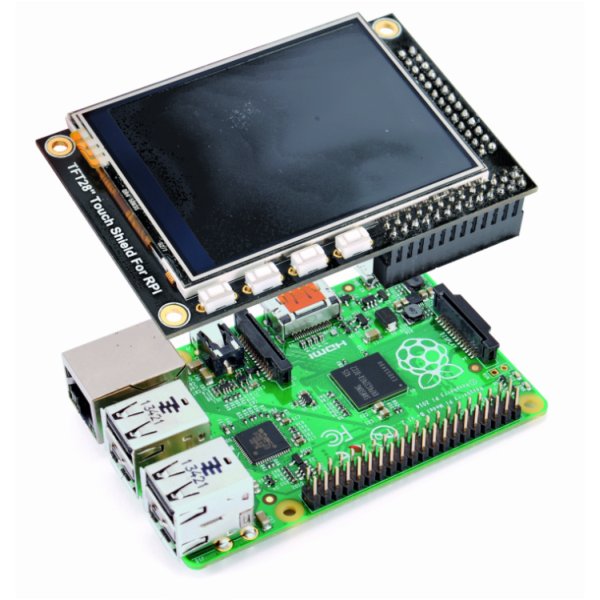
Setting the backlight level
The backlight of the TFT display is done through four LEDs which absorb a total of about 75 mA. If we power the board through battery or if you still want to turn the backlight off, the STMPE610 touch controller has two I / O pins and one of these is connected to the transistor that controls the backlight. This pin is accessible from the command line as a Raspberry Pi GPIO terminal, recognizable as GPIO 252. To access the GPIO you must export its device file with the command:
echo 252 > /sys/class/gpio/export
with:
ls -l /sys/class/gpio
You can check the actual existence of the GPIO. We declare the pin I / O as output with the command:
echo ‘out’ > /sys/class/gpio/gpio252/direction
Now we turn the backlight on by setting the pin value to “1″ with the command:
echo ‘1’ > /sys/class/gpio/gpio252/value
To turn off the backlight, use the opposite command:
echo ‘0’ > /sys/class/gpio/gpio252/value
Writing an app
What can we do with such a nice display, other than managing Raspberry Pi console or desktop GUI? We can write our applications, to communicate with the GPIO and any other external sensors. The possibilities are so many.
But if we want to develop a very simple starting application, we have to reduce this possibilities, always doing something really interesting. We will use Python to create a graphical interface that can control the IN/OUT shield outputs. To interact with the TFT graphic display we will exploit the functionality available in pygame, the library to create video games and graphics applications in general. In recent Raspbian distributions, pygame library is already included and installed. If not, we install it through the Manared Python Package named “pip” (pips Installs Python), with the command:
pip install pygame
If we had not “pip” installed, install it with the command:
Apt-get install pip
Done? Check the installation by using python from the command line. We check that everything is working by typing one after another the following instructions:
import pygame
import os
os.putenv(‘SDL_FBDEV’, ‘/dev/fb1′)
pygame.init()
lcd = pygame.display.set_mode((320, 240))
lcd.fill((255,0,0))
pygame.display.update()
pygame.mouse.set_visible(False)
lcd.fill((0,0,0))
pygame.display.update()
Among the important instructions, see the one that sets the fb1 device as framebuffer, the pygame library init. After, we set the display definition we called “LCD” with resolution of 320 x 240 pixels. The other instructions change the screen background color, using the usual RGB coding. We conclude with one last little project that allows us to command four relays with touch controls on the TFT display. We use the RELAY4CH–2846 board (available from Futura Elettronica) which hosts four relays, is powered at 5 volts and is drivable with direct or optocoupled digital inputs: those accept voltages from 1.5 to 5V and therefore are compatible with the Raspberry Pi GPIO output. We choose the direct coupling by placing a jumper on the COM and GND terminals. Now connect the card to Raspberry Pi as in the diagram in figure.
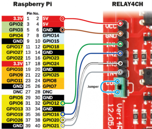
We connect the power supply and four GPIO pins driving the relays. We chose GPIO12, 16, 20 and 21 pins, very convenient to connect on the B+ version GPIO.
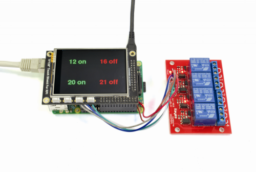
To power up the board weld a strip of male connectors on the GPIO “replica” present on TFT module using pins 2 (positive) and 6 (mass) with female-female cables. In Listing 1 we see the program to drive the relays. It is always a Python program. For the graphical interface we used the pygame library, which we have just described. The list is full of comments. The code logic is the initial construction of the graphic interface. The dictionary contains the central position coordinates where we want each pin description. The “for” loop outside the main loop prepares the display area with the writings for the four pins. The word “off” is added to each pin’s “name”. The whole is colored in red and positioned so that the center corresponds to the coordinates contained in the dictionary. Finally, the display is refreshed and the text become visible. When the code is running, if you tap on a pin name the corresponding relay changes state while the text color indicates its current status: red if off and green if on, as shown in the photo of figure.
In future posts we will see how to use the display with other shields and with extended functionality, like the ability to operate a device directly from the display or from a webpage.
For now, just enjoy experimenting.
Listing 1
#!/usr/bin/python
# TFT_Rele.py.py
# Import librerie
import pygame
from pygame.locals import *
import os
from time import sleep
import RPi.GPIO as GPIO # GPIO management library
# set pin as output
GPIO.setmode(GPIO.BCM) # uses GPIO enumeration
GPIO.setup(12, GPIO.OUT) # Set pin as OUTPUT
GPIO.setup(16, GPIO.OUT)
GPIO.setup(20, GPIO.OUT)
GPIO.setup(21, GPIO.OUT)
GPIO.output(12, False) # set pins to off
GPIO.output(16, False)
GPIO.output(20, False)
GPIO.output(21, False)
# color definitions (R, G, B)
WHITE = (255,255,255)
RED = (255,0,0)
GREEN = (0,255,0)
BLACK = (0,0,0)
# system variables to define the device, the
# display and touchscreen
os.putenv('SDL_FBDEV', '/dev/fb1')
os.putenv('SDL_MOUSEDRV', 'TSLIB')
os.putenv('SDL_MOUSEDEV', '/dev/input/touchscreen')
# relays initial status
pin12='off'
pin16='off'
pin20='off'
pin21='off'
#init pygame
pygame.init()
# hydes the mouse pointer from display
pygame.mouse.set_visible(False)
lcd = pygame.display.set_mode((320, 240))
# black screen
lcd.fill(BLACK)
pygame.display.update()
# set font
font_big = pygame.font.Font(None, 50)
# dictionary Key=pin value=coordinate writing center
touch_buttons = {'12':(80,60), '16':(240,60), '20':(80,180), '21':(240,180)}
# set the initial screen status
for k,v in touch_buttons.items():
b = k + ' off' # Scritta con pin + off
text_surface = font_big.render('%s'%b, True, RED) # red text
rect = text_surface.get_rect(center=v) # centers the text
lcd.blit(text_surface, rect) # put text on the display
pygame.display.update()
# main program loop
while True:
# waiting display event
for event in pygame.event.get():
if(event.type is MOUSEBUTTONDOWN): # Display tapped
pos = pygame.mouse.get_pos()
print pos
elif(event.type is MOUSEBUTTONUP): # finger released from display
pos = pygame.mouse.get_pos() # recall finger position
print pos
# reckon which quarter of the display is the finger
x,y = pos
if y < 120:
if x < 160: # up and left
print 12
v = touch_buttons.get('12') # finds text center
if pin12 == 'off': # if off
pin12 = 'on' # sets to on
GPIO.output(12, True) # pin level high
b = '12 on' # on text
color = GREEN # Color green
else:
pin12 = 'off'
GPIO.output(12, False)
b = '12 off'
color = RED
else: # up and right
print 16
v = touch_buttons.get('16')
if pin16 == 'off':
pin16 = 'on'
GPIO.output(16, True)
b = '16 on'
color = GREEN
else:
pin16 = 'off'
GPIO.output(16, False)
b = '16 off'
color = RED
else:
if x < 160: # down and left
print 20
v = touch_buttons.get('20')
if pin20 == 'off':
pin20 = 'on'
GPIO.output(20, True)
b = '20 on'
color = GREEN
else:
pin20 = 'off'
GPIO.output(20, False)
b = '20 off'
color = RED
else: # down and right
print 21
v = touch_buttons.get('21')
if pin21 == 'off':
pin21 = 'on'
GPIO.output(21, True)
b = '21 on'
color = GREEN
else:
pin21 = 'off'
GPIO.output(21, False)
b = '21 off'
color = RED
# draw the right display portion
# and updates it
text_surface = font_big.render('%s'%b, True, color)
rect = text_surface.get_rect(center=v)
lcd.fill(BLACK, rect) # delete the previous text
lcd.blit(text_surface, rect) # Place the new text
pygame.display.update() # redraw the display
sleep(0.3) # waits
GPIO.cleanup()
# TFT_Rele.py.py

# Import librerie

import pygame

from pygame.locals import *

import os

from time import sleep

import RPi.GPIO as GPIO # GPIO management library

# set pin as output

GPIO.setmode(GPIO.BCM) # uses GPIO enumeration

GPIO.setup(12, GPIO.OUT) # Set pin as OUTPUT

GPIO.setup(16, GPIO.OUT)

GPIO.setup(20, GPIO.OUT)

GPIO.setup(21, GPIO.OUT)

GPIO.output(12, False) # set pins to off

GPIO.output(16, False)

GPIO.output(20, False)

GPIO.output(21, False)

# color definitions (R, G, B)

WHITE = (255,255,255)

RED = (255,0,0)

GREEN = (0,255,0)

BLACK = (0,0,0)

# system variables to define the device, the

# display and touchscreen

os.putenv('SDL_FBDEV', '/dev/fb1')

os.putenv('SDL_MOUSEDRV', 'TSLIB')

os.putenv('SDL_MOUSEDEV', '/dev/input/touchscreen')

# relays initial status

pin12='off'

pin16='off'

pin20='off'

pin21='off'

#init pygame

pygame.init()

# hydes the mouse pointer from display

pygame.mouse.set_visible(False)

lcd = pygame.display.set_mode((320, 240))

# black screen

lcd.fill(BLACK)

pygame.display.update()

# set font

font_big = pygame.font.Font(None, 50)

# dictionary Key=pin value=coordinate writing center

touch_buttons = {'12':(80,60), '16':(240,60), '20':(80,180), '21':(240,180)}

# set the initial screen status

for k,v in touch_buttons.items():

b = k + ' off' # Scritta con pin + off

text_surface = font_big.render('%s'%b, True, RED) # red text

rect = text_surface.get_rect(center=v) # centers the text

lcd.blit(text_surface, rect) # put text on the display

pygame.display.update()

# main program loop

while True:

# waiting display event

for event in pygame.event.get():

if(event.type is MOUSEBUTTONDOWN): # Display tapped

pos = pygame.mouse.get_pos()

print pos

elif(event.type is MOUSEBUTTONUP): # finger released from display

pos = pygame.mouse.get_pos() # recall finger position

print pos

# reckon which quarter of the display is the finger

x,y = pos

if y < 120:

if x < 160: # up and left

print 12

v = touch_buttons.get('12') # finds text center

if pin12 == 'off': # if off

pin12 = 'on' # sets to on

GPIO.output(12, True) # pin level high

b = '12 on' # on text

color = GREEN # Color green

else:

pin12 = 'off'

GPIO.output(12, False)

b = '12 off'

color = RED

else: # up and right

print 16

v = touch_buttons.get('16')

if pin16 == 'off':

pin16 = 'on'

GPIO.output(16, True)

b = '16 on'

color = GREEN

else:

pin16 = 'off'

GPIO.output(16, False)

b = '16 off'

color = RED

else:

if x < 160: # down and left

print 20

v = touch_buttons.get('20')

if pin20 == 'off':

pin20 = 'on'

GPIO.output(20, True)

b = '20 on'

color = GREEN

else:

pin20 = 'off'

GPIO.output(20, False)

b = '20 off'

color = RED

else: # down and right

print 21

v = touch_buttons.get('21')

if pin21 == 'off':

pin21 = 'on'

GPIO.output(21, True)

b = '21 on'

color = GREEN

else:

pin21 = 'off'

GPIO.output(21, False)

b = '21 off'

color = RED

# draw the right display portion

# and updates it

text_surface = font_big.render('%s'%b, True, color)

rect = text_surface.get_rect(center=v)

lcd.fill(BLACK, rect) # delete the previous text

lcd.blit(text_surface, rect) # Place the new text

pygame.display.update() # redraw the display

sleep(0.3) # waits

GPIO.cleanup()
Source: Touch Display for Raspberry Pi