
1 Executive Summary
The document at hand describes the motivation, research, design and prototyping
completed for the Senior Design 1 Semester at the University of Central Florida. The
following will go into very detailed and rigorous amounts of information concerning the
development of the Smart Mirror project of which Group 8 decided to take on as their
project for two semesters. Four to five years of learning different areas of the Electrical
and Computer Engineering field boils down to two semesters of a laborious project that
inevitable will work flawlessly at the end of the second semester of work. The Smart Mirror
system that is to be developed by this team of four is a project that has been seen on the
internet before. However, the goal of this last course at the University of Central Florida is
to challenge a team of creating something unique that folks have never seen before. This
team has added some new and exciting features to the Smart Mirror that have not been seen
before. By doing so, the team is able to fully demonstrate their abilities to cooperatively
work as a team and come up with new and innovative ideas for this project as well as those
encountered in their future careers.
The Smart Mirror is designed to be a technological addition into the lives of a wide range
of users by providing a unique experience while viewing their appearance. Through the use
of a one-way mirror, a display mounted on the rear surface will allow for select content to
be seen through the mirror by the user, while the rest of the surface appears as a
conventional mirror’s reflective surface.
This mirror will be outfitted with electrical and computing components to display functions
such as the time, weather, and social media feeds in an unobtrusive manner. Rather than
designing a passive system which does not accept any input, the mirror will obtain sensor
data from both the outside world and the user to determine the state in which it should
currently exist.
Power savings methods will be implemented to detect when a user is no longer present and
shut down unnecessary systems such as the LCD display. When a user approaches the
mirror, the system will wake to display data on the screen, as well as utilize facial
recognition to attempt to log in to that specific user’s social media account and mirror
settings.
While the user is in front of the mirror, a gesture sensor will accept input from the user to
swipe through different feeds. Additionally, light levels will be monitored such that periods
of low ambient lighting will result in LED assistance from strips mounted on the front of
the frame. This not only serves the purpose of allowing the user to better view their
appearance, but also creates a better environment to obtain images for the facial recognition
system.
While similar products currently exist from single party developers, the aim of this project
is to improve upon the work which has been completed to create a better experience for the
end user. Through the addition of the aforementioned facial detection, power management,
and user input, our group is striving to create a more complete platform that can also be
further developed upon by electronic hobbyists in the future in an open source
methodology.
2 Introduction
The following document provides an in depth look at the design and testing stage of the
University of Central Florida’s Senior Design final project for Group 8. Over the course of
the semester, our group has faced real-world engineering decisions with relation to
implementation, financial, technical, and time constraints. The goal of this final design
course is to showcase the engineering knowledge that UCF has offered in its curriculum
over the four years of attendance in a method that is similar to what will be experienced in
a full-time job environment. While numerous classes have prepared students for working
in groups and solving problems both together and separately, this course demands high
levels of effort to fully complete the development of a finished product. Apart from
graduating with soft skills such as working in a small team, the course also intends to allow
students to delve deeper within their areas of technical interest to better understand the
principles and concepts that will be expected from within the industry.
With that being said, students have the ability to choose what interests them most in the
project and run with it. Using the resources provided to us by the University of Central
Florida, the students can research their respective area of interest and develop new and
innovative solutions to problems in the project. Even the simplest of ideas within projects
can create problems that no student has ever been exposed to. This kind of technical
practice prepares an individual for the complex and technical difficulties that may appear
during ones’ career.
As the following document is designed to be an intermediary step in the complete process,
the finished product is currently under development. Come the end of Spring of 2017, the
Smart Mirror project will be a completely developed system ready for showcase to the
engineers and professors at the University of Central Florida, as well as current students
and industry experts.
3 Project Description
This section will describe the project in its entirety. It will explain the motivations the team
had for pursing the project, as well as any goals hoped to achieve by the members. This
section will also outline the specifications the team has set for this project. The
specifications sections will then go into more detail on each aspect of the project and the
goals that should be met. Lastly, a house of quality diagram will be included to visually
show the tradeoffs expected in this project.
3.1 Project Motivation and Goals
The motivation behind this project was building a device that is interesting to the team. We
wanted to design something that excited us, and that we would want to use. Because our
team is two electrical engineers and two computer engineers, not one area of interest was
focused on. We wanted to learn more in our respective fields from this project, including
designing hardware circuits and also computer vision. There was a large interest in the
group for computer vision software, which lead to the addition of the facial recognition
software.
While the Smart Mirror is a DIY project that already exists, we saw an opportunity to make
it better. This device was interesting to us from the start, but the additions we thought of
adding such as facial recognition and gesture control are what drove us to pursue this
project. On the electrical engineering side, this would allow us to design our own circuits,
including a power supply circuit and supporting circuits for various sensors and a
microcontroller. It will give us the chance to learn more about the process of searching for
specific components and parts needed to fulfill certain requirements.
On the software side, improvements are being implemented to both the existing open
source framework as well as adding support through additional modules. By adding the
software support for the additional subsystems, the final product will implement additional
features outside those which are currently released. Motivations for adding the additional
software were fueled by the desire to practice the engineering related concepts which have
been taught throughout the past four years in higher education. Between concepts learned
through various internships in the corporate engineering environment, to specialized
technical elective courses outlining additional details in the field, practicing these select
skills to fully realize a full system’s prototype will collectively reinforce the key skills
required by the industry.
As each team member approaches graduation, leaving lasting impressions on the faculty
and guests of the senior design showcase will assist in developing an extensive network of
industry professionals. By selecting a project which highlights both computer and electrical
engineering within the college, it is believed that the impression left based on the
technology used in this project will be a positive one. By developing this network, potential
full time engineering positions may be obtainable and solidified further down the career
paths of each contributing team member.
The team saw an opportunity to improve an existing idea. The idea of a Magic Mirror had
been shown with date, time, compliments and facial overlays. The team had not seen it
implemented previously with multiple users or facial recognition. This would be a great
exercise in adding to an existing architecture, debugging, and new implementation. Also,
it allows for an opportunity to learn about different architectures, languages and critical
thinking techniques. These are all vital characteristics of being a developer – regardless of
field. Very often, an engineer will be asked to take an existing idea and improve upon it.
This means the engineer must put themselves in the same mindset of the previous
developers and use the existing tools to improve the architecture. This exercise will allow
the team to use these skills and improve upon them.
Overall, the motivations for completing such a project can be summed up as a desire to
enhance a currently underdeveloped product with the team’s own implementations and
solutions, while showcasing the engineering skills each team member has obtained while
in attendance at the University of Central Florida.
3.2 Objectives
The main objective of the Smart Mirror project is to design and retrofit a mirror with
supplemental technology which will provide the user with relevant information during day
to day life. Meeting this objective will entail creating a complete system to meet the project
specifications in a manner which also remains user friendly. By implementing various
features which have yet to be implemented on commercial smart mirrors, the final product
will be a culmination of subsystems working in unison to provide a unique experience and
addition to the lives of potential proponents.
The project’s secondary objective entails implementing face recognition software to detect
and identify the user. This will allow personalized information to be provided on screen
based on the current person using the mirror by utilizing preconfigured credentials to
retrieve information from social media news feeds.
The third objective is to implement power saving technology into the Smart Mirror in an
effort to make it as efficient as possible. While other relevant projects have strived for
practicality when designing similar products, this team is determined to create one that is
both practical and efficient. Thus, making it a marketable product by making it appealing
in more than just one way.
The final objective is to create a system which responds to user input. Rather than
implementing a passive system, the project will utilize various sensors to respond to the
environment. User presence detection, adaptive lighting control, and gesture interpretation
will be designed into the system to create the next level of available smart mirror features.
3.3 Requirement Specifications
The following requirement specifications outline details for various components and
subsystems which are to be implemented in the final design. By first creating a list of
specifications, the team was able to properly compare and contrast various products
existing on the market before making final decisions. Understanding the role that each
component played within both the subsystem and the system as a whole allowed for a
culmination of key requirements to properly ensure that the project requirements could be
met. Additionally, compatibility among devices is an important consideration further
solidifying the necessity of developing strong requirement specifications early in the design
stage.
3.3.1 Project Specifications
- The following product specifications define the requirements to be implemented in the
- Smart Mirror. The specifications defined using the word “shall” are hard requirements that
- team will meet by the end of the second semester of the Senior Design course. The
- requirements that use the word “should” are a stretch goal set forth by the team. All efforts
- will be made to accommodate these goals, but is it not expected from our advisor that these
- need to be met. With that being said, you can still see in the following requirements for the
- project that most utilize the word “shall” meaning there are a lot of features that the Smart
- Mirror will have for the completed design.
- The following product specifications define the requirements to be implemented in the
- Smart Mirror.
- The Smart Mirror shall be within the boundaries of 22x22x5 inches
- The Smart Mirror shall not exceed 10lbs
- The Smart Mirror shall allow the user to view their appearance
- The Smart Mirror shall be powered via a single cord
- The Smart Mirror shall connect to a user’s Wi-Fi
- The Smart Mirror shall display the following information:
- o Current Time
- o Current Date
- o Weather Forecast
- o News Feed
- The Smart Mirror shall enter a power saving mode when no user is detected after 2
- minutes
- The Smart Mirror shall wake and power on the display when a user is detected
- The Smart Mirror shall utilize facial recognition software to:
- Determine the user
- Show data applicable to their account
- The Smart Mirror should allow a user to scroll through their news feed
3.3.2 Microcomputer Specifications
- The Microcomputer shall be network compatible
- The Microcomputer shall support graphic outputs to support LCD displays
- The Microcomputer shall be capable of handling multiple, simultaneous process
- The Microcomputer shall support serial communication with the selected
- microcontroller
- The Microcomputer shall interface with a camera to obtain user images
3.3.3 Microcontroller Specifications
- The Microcontroller shall be compatible with the Arduino bootloader and support
- the brand’s programming
- The Microcontroller shall support serial communication abilities via UART and
- I2C
- The Microcontroller shall be powered by 5VDC or less
3.3.4 Camera Specifications
- The camera shall be capable of capturing images with adequate resolution for facial
- recognition
- The camera shall be compatible for use with the microcomputer
- The camera shall have a small footprint and size with relation to the mirror
3.3.5 Lighting Specifications
- The LEDs shall require a voltage no greater than 12VDC
- The LEDs shall include the capability to dim, whether natively supported or by
- external circuitry
- The LEDs shall output white light and not rely on RGB combinations to appear
- white
- The LEDs shall output light levels capable of lighting a user’s face from one to two
- feet away
3.3.6 Power Specifications
- The power system shall accept an input of 12V DC
- The power system shall provide a 5V rail for the microcomputer, microcontroller,
- and sensors
- The power system shall provide a 3.3V rail for the logic level converter between
- the microcomputer and microcontroller.
- The power system shall utilize power efficient devices to reduce energy waste.
- The power system shall consume less power while under less load.
3.3.7 Presence Sensor
- The presence sensor shall interface with the microcontroller via serial
- communication
- The presence sensor shall detect the distance of a user within zero and two feet
- The presence sensor shall be powered with no greater than 5 VDC
- The presence sensor shall be capable of mounting on the frame
- The presence sensor should support multiple functionalities
3.4 House of Quality Analysis
The House of Quality is a unique tool used to visualize how the product or service will
relate to the consumer. It contains market desires, customer desires, relationships between
the two and sometimes more. The main aspect of this tool is to show the correlations
between these wants and requirements from the customer, market and provider. These
correlations can help give the producer of a good or service a good idea of how their
product could be designed or delivered.The House of Quality for the Smart Mirror is shown
below in Figure 1.
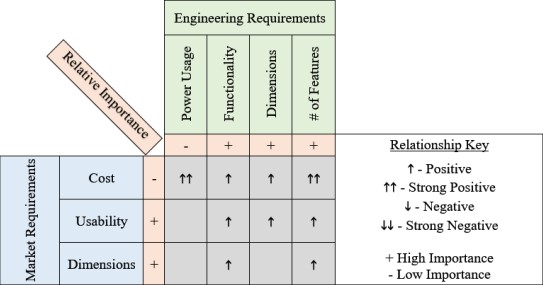
One of the most important Market requirements is the cost of the product. This is one of
the driving factors when it comes to designing a successful product. If the product is very
expensive, it should contain a significant amount of quality such that it is still appealing to
the customer. If the product is cheap, then the required effort and materials may not have
been put into the product and this alone would make it unappealing to any customer and
some competitors may view it as an advantage to their product/company. The cost to build
the Smart Mirror is estimated to be around $600, but the development and build will most
likely not come to that amount since the estimates for components are high.
This Usability of the product will also impact the market and engineering requirements.
The higher the usability of the product or device, the better chance it will be successful on
the market as well as profitable to the company producing it. For the Smart Mirror
specifically, another important market requirement is the dimensions of the product. For
this to be a successful product on the market, the mirror cannot be too large that it would
not fit in someone’s house. It would also likely drive the cost of the product through the
roof! Too small of a mirror and the user would not even be able to seem themselves let
alone the information that is to be displayed on the mirror.
When brainstorming the design for this Smart Mirror, four key engineering requirements
were taken into consideration. The first one being power usage. Being that this is a device
that would likely stay plugged in at all times or even have a hard-wire installation it needs
to have some sort of power saving technology. This is obviously going to increase the cost.
One of the specifications set forth by the team is to have the Smart Mirror pull less than 4
amps of current at any point in time.
The next engineering requirement on the chart is functionality. This one might be the most
important one when it comes to the engineering requirements and relating them to the
market requirements. If the functionality of the Smart Mirror is substantially above its’
competitors it will do well on the market. Of course, functionality will increase the
usability, cost and most likely the dimensions.
Dimensions is on both the engineering and market requirements. When designing the
product, the size needs to watched carefully. It is easy to say there will be enough room for
any certain component. However, in the end there may not end up being enough room. So,
monitoring the dimensions of the Smart Mirror will directly influence the cost and usability
of the device. The Smart Mirror that is explained throughout the remainder of the document
has a dimension restriction of 22x22x5 inches.
The number of features that the Smart Mirror will have is one of the engineering
requirements made to give the device a unique aspect to it. Adding the one-of-a-kind facial
recognition is among many of the features on the Smart Mirror. This was something that
definitely increased the cost of the product, but also increased the usability of it which
appeals to consumers quite nicely.
4 Research
Before beginning such an involved project, research is required in order to build up a good
background and understanding of what is needed. Research done by each engineer will be
determined on what parts of the project they are responsible for or interested in. For the
electrical engineers this consists of all hardware components, as well as design techniques.
The computer engineers researched various techniques for communication, facial
recognition, and the architecture that will ferry messages between the hardware and the
Internet. Time was also taken to look into devices are products that already exist that are
similar to ours. This is an important aspect not only to generate ideas for our own mirror,
but also to make sure our device is different from the others and provides benefits that they
cannot.
4.1 Existing Technologies
When designing any project, it is important to keep in mind any similar existing products.
The Smart Mirror is not an original concept. A popular DIY version exists as well as a few
consumer products. The following section will look at a few of these existing devices and
how they influence our design.
4.1.1 Magic Mirror
The Magic Mirror is a DIY project designed by Michael Teeuw. This design was the main
influence of our Smart Mirror. The Magic Mirror allows users to view the weather in their
area, their calendar, the local news, and provide a compliment. The mirror works by having
a display monitor display information behind a two-way mirror. The two-way mirror
allows the information (white text) to be seen from the other side, while still reflecting the
user’s appearance. Teeuw designed a webpage that would constantly update with all the
information to be displayed. The webpage is a simple design, white text on a black
background, in order to be seen through the mirror. A Raspberry Pi is used in connection
with the display monitor to show the webpage. In order to power the project, Teeuw found
a monitor with USB ports and used that to power the Raspberry Pi. The biggest influences
of the Magic Mirror on this project are the mirror design and the open source software. The
use of a two-way mirror with a display monitor behind was adopted, but rather than use a
monitor the same size of the mirror, one just big enough to display information will be
used. The open source software Teeuw has provided will also be used as a base line for the
Smart Mirror software, with additions being added to it.

4.1.2 Toshiba’s Multi Display in Black Mirror
Toshiba showed a smart mirror concept at CES 2014 that they called “Multi Display in
Black Mirror”. They had two versions, one for the bathroom and one for the kitchen. The
bathroom version allows the user to view daily information such as the local weather and
fitness information pertaining to the user. The kitchen version allowed the user to create
recipes or view ones already stored on the database and assist in the cooking process. The
most interesting function of this product was the ability to use gestures to interact with the
mirror, similar to the Xbox Kinect. This is to be implemented in the Smart Mirror as a way
of navigating panes of information.
4.1.3 Samsung’s ML55E
Samsung has their own smart mirror geared towards being used in hair and beauty salons.
The ML55E has the typical features of smart mirrors like time and weather but also
includes some additional features. Through a phone app, the display can be customized to
show information such as advertisements and promotions for the salon. A key feature of
this particular display that is relevant to our project is the use of a proximity sensor. When
a customer is not sitting in front of the mirror, the display takes up the whole mirror, making
the advertisements readable for customers who are in the waiting area. Once a customer is
sat in front of the mirror, it becomes more like a mirror, and all display graphics are moved
to the sides of the screen. This project plans to use a proximity sensor as well. The
proximity sensor will be used to determine when the user is in front of the mirror, but unlike
the ML55E, the mirror will not be displaying anything while not in use. This is to make
the mirror fit into common home décor while not in use.
Panasonic’s Smart Mirror
Panasonic debuted their version of the smart mirror at CEATEC in Japan. Their version
has a slightly different spin than all the other mirrors researched. The mirror was designed
to be used in beauty and make up store. The main drawing feature of the mirror is the ability
to tell you what is wrong with you face. It can point out flaws such as redness, wrinkly
skin, and pores. The mirror can then recommend beauty products that the store carries that
can be used to hide these blemishes. The camera does this by taking a picture and analyzing
it. There is also a version of Panasonic’s smart mirror that will give you a makeover by
showing what certain projects will look like on your face. Our project will also feature the
use of a camera in order to recognize what users are in front of the mirror.
The following research section highlights the relevant technologies and engineering related
concepts which may be utilized within the development and implementation of the Smart
Mirror. While an explanation of each technology is present, initial decisions regarding the
different implementations may also be found, playing a part later in component selection.
By first researching and understanding the existing technology which can be utilized in the
system, the team has been able to make educated decisions with respect to technical
concepts and options available.
TTL Serial Logic Levels
When working with embedded devices which must communicate with one another over a
physical connection, considering the voltage logic level at which they operate is crucial.
As a computing device, calculations are completed by both driving transistors in the circuit
to a high voltage and pulling them low to ground, representing the 0 and 1 bits. One
differentiating factor between devices is the transistor-transistor logic (TTL) voltage ranges
which are used to differentiate the value of the bit.
If logic levels were implemented where 0 bits are represented by only 0v, and 1 bit are
represented by only Vcc, numerous false readings and false transmissions would occur on
the transistor level. Due to imperfections in circuitry and outside noise interfering with the
system, it cannot be guaranteed that the voltage levels will be accurate in such a precise
sense. Instead, an acceptable level of voltage ranges must be defined in which the device
will accept a 0 bit as existing within a predefined range around the 0v ground. Similarly,
an acceptable range for the 1 bit must be established as a range around Vcc.
I2C
The I2C communication protocol is a popular technology due to its robust nature of
acknowledgments between a master and slave devices. The protocol relies on just two
wires for communicating with up to ~112 devices. Two signal wires, SCL and SDA, are
used for communication. The two signal wires are considered to be open drain since pull
up resistors are used to pull the signal high when the devices are not communicating, and
the devices will pull the signal low during communication. During design, a master device
must be selected as the device which initiates all communication between itself and the
slave devices.
With I2C communication, every device is designated as a Master or a Slave. In most
implementations, a system will consist of a single master device which drives the SCL
clock line and initiates all communication with slave devices. Slave devices act as
responders to the requests being made by the master device. Each slave is assigned a
specific address so that the master is capable of selecting the device it wished to
communicate with. Since only a single master device exists within the system, conflicts
between devices cannot exist due to the nature that slave devices are unable to initiate
transfers of data.
When a master device requests data from a slave device, a specific pattern of bit sequences
must be adhered to. The data can be divided into 8-bit sequences of request and response
between the master and slave. To begin, the master must transmit a start sequence along
the SCL and SDA communication lines. The start sequence is defined by holding the SCL
clock line high while the SDA data line is allowed to change from high to pulled low. As
will be addressed in the future, this is significantly different than the data transmission
stage where the SDA line must remain constant during a high clock cycle.
Following the start sequence, the master device will transmit a 7 bit sequence containing
the address of the slave device in which it will be requesting communication with followed
by a read/write bit. Due to the 7 bit addressing sequence, there are 128 possible addresses,
but I2C reserves certain addresses for specific functions, decreasing the number of possible
devices to 112 as previously mentioned. The 7 bit address is sent with the most significant
byte first, ending with the least significant byte. The final byte of the first 8 bit sequence is
the read/write bit, indicating the operation the master wishes to conduct on the slave.
Following the first 8 bit sequence addressing the device the master wished to communicate
with, the master device will relinquish control of the SDA data line for use by the slave
device. The slave device sends an acknowledgement to the master by pulling the SDA line
low, as a way of stating that it has received the message and is prepared for the next stage.
In the case that the acknowledgement bit is not sent, the master device must decide how to
proceed with the operation.
The master device will continue to pulse the SCL clock line at a regular interval while data
is transmitted over the SDA until a stop bit is transmitted. The stop bit is the opposite
operation of the start bit, where SDA must be allowed to return to high from being pulled
low by the device during a point in time where the SCL clock line is high.
UART
UART Serial Communication, is a peer-to-peer asynchronous protocol in which two
devices communicate using two signal lines. The universal asynchronous receive/transmit
protocol is an intermediate serial stage used to connect the parallel interfaces of two
devices. This is completed by shifting out a bit sequence from a register and transmitting
the data bit by bit across the signal lines, where the receiving device will shift in the data
bit by bit at the same rate as transmission. In short, the parallel data is converted to serial
data by the transmitter, and serial data is converted to parallel data by the receiver. Unlike
I2C, a device can act as both a receiver and a transmitter in the same system and is not
assigned a set role.
Key concepts in understanding the UART communication method lie in first recognizing
that the protocol is asynchronous. Asynchronous communication is defined as the
transmission of data intermittently between two devices rather than a continuous data
stream with an external clock governing the transfer. In this design, the devices are
permitted to complete internal processor operations and query the UART buffer when the
data is desired, rather than yielding the current operation to service the communication.
The following discussion explains in detail the concepts used in UART communication
and the differences between this communication protocol and I2C.
The two lines used for communication are the TX transmit and the RX receive data lines.
Unlike I2C, a clock line is not required. Within each device’s UART exists a clock
generator to keep the proper timing baud rate for reads and writes to the signal lines.
Typical baud rates are 9600 bits per second, but are capable of reaching up to 115200 bits
per second if such speeds are required for the application.
UART data is transmitted in the form of packets between the transmitter and receiver.
Similar to the I2C method, a 1-bit start signal is used to signify the beginning of
transmission by the transmitting device pulling the TX line low during a clock cycle.
Following the start bit, the data bits are then transferred, typically 8 bits followed by a
parity bit. Following the parity bit, a stop bit sequence of at least two clock cycles is used
to signify the end of transmission.
Parity bits are used by the receiver to check for errors during transmission that may have
been incorrectly changed along the path from the transmitter to receiver. UART utilizes a
parity bit based on the count of bits that were set to high. The transmitting device is aware
of the count of high bits in the data frame it is transmitting and sets the parity bit to 0 if
there is an even number of 1 bit and sets the parity bit to 1 if there is an odd number of 1
bit. The receiver compares the parity bit to the information it received and if there is a
mismatch between the data, it can conclude that a bit must have been corrupted during
transmission. The system will then handle the error, possibly by requesting a
retransmission.
Select advantages of this method include no clock signal line required, a parity bit is used
to check errors, and that the protocol is well documented for use between microcontroller
units. Disadvantages include limited data frame size, and the lack of support for
connections between multiple devices. For this project’s implementation, the
disadvantages hold little weight as multiple connections are not required, and the ATmega
and Raspberry Pi are capable of holding stable clocks and therefore stable baud rates.
Pulse Width Modulation
Pulse Width Modulation (PWM) is a digital, modulated, square waveform typically utilized
in control circuitry and implemented in a wide variety of applications. For example, it can
be used to control servos, analog circuits, or dim LEDs.
PWM signals take the shape of a square waveform with alternating values of high and low
voltages. Based on the clock cycle time of the microcontroller, a duty cycle can be used to
describe the amount of time the signal is kept high compared to the overall cycle time of
the signal. Based on the selected duty cycle and the high voltage level, it is possible to
calculate the average voltage output by the system by simply multiplying the duty cycle
percentage value times the high voltage level.
In the application of the project, a PWM signal will drive a MOSFET circuit to dim the
LEDs on and off, rather than simply applying a high or low signal. Using this method, the
user will not be startled or blinded by sudden bright lights illuminating the space, but
allowed to adapt to the changing levels as the voltage applied to the LEDs gradually
increases.
Power Supply
When designing any project one must decide on what type of power supply will be used to
power the device. There are multiple ways a device can be powered including by battery,
AC to DC power supplies, and via USB. All three of these options are viable for most
projects, so selecting one would depend on one’s project requirements including mobility,
power requirements, and need of a constant voltage. Research was done on these three
power sources to determine which option was the best fit for the Smart Mirror.
Power that is supplied by batteries allows a project to be mobile. Without the need to be
connected to AC supply like a wall outlet, a device can be used wirelessly and is not
restricted by location. There are many different battery technologies that can be used and
one would need to consider the power requirements of their project and select a battery
with the proper capacity. Capacity is given in amperes per hour, so the capacity of a battery
tells you how many amps the battery can supply for an hour while fully charged. If a battery
power supply is chosen, then the size and weight of the battery must be considered. If a
device is meant to be mobile a heavier battery might not be ideal. A downside to batteries
is the need to recharge. If it is essential that a device be constantly operating, batteries are
not the appropriate supply.
A second form of power supply is via USB. This option is highly recommended for devices
that work in tandem with a laptop, computer, or other electronic device. The USB
connection is simple and easy to implement in a project. For projects that talk with
computers or other devices through USB, powering through USB as well is an obvious
choice as it reduces the amount of cables needed for the project. This method is not useful
for devices that do not operate alongside a computer.
A third option for the power supply that was researched is an AC to DC power supply.
These devices are commonly used by computers and laptops to convert the AC power that
is supplied by a wall outlet into DC power in order to power or charge the device. This
technology is useful as the supply outputs a regulated DC voltage and current, which you
can design your project around. This style of power supply comes in the form of a wall
adapter with the AC to DC converter either at the point of contact with the outlet, or further
down the cable in the form of a power brick. These converters are commonly found and
should be chosen based on the voltage and current requirements for the project. Because
the adapters are so commonly found, they tend to be very budget friendly options. The
disadvantage of this form of power supply is the need to be connected to an outlet. This
restricts the mobility of the device and also adds a wire to the device, eliminating wireless
capabilities.
If an AC to DC power supply were to be used, the type of connection would need to be
decided as well. The first type of connection researched is a DC barrel connector. This
common connection is typically found in inexpensive electronics. The male side of the
connecter is usually found on the end of a wire and the female side mounted to the device
PCB. The female connector has at least two pins with an optional third that can be used to
detect when a male plug is inserted. The other two pins are commonly named the “tip” and
“sleeve”. There are three variables to consider when selecting a barrel connector. The
sleeve diameter, the pin diameter (which is dependent on the sleeve diameter), and the
polarity. The polarity refers to the voltage of the tip compared to the sleeve. Positive
polarity is the common type, but negative could also be used.
Another option researched is the Molex connector. The name “Molex” comes from the
company that originally designed the connector, but has become the general term for all
similar connectors. This connection has multiple pins and is rated for high current as each
pin can supply up to 11A per pin. This feature makes Molex connectors common in high
power projects. The female connector is actually found on the cable and the male side on
the board. The pins of the male side fit very tightly into the female side in order to keep
devices from losing power. The more the plug is detached, the looser the hold gets on the
pins, making this not a good option for devices that frequently change connections.
JST connector was another technology that got its name from the company that first
designed it. This connection is small (2mm) and takes up very little PCB space. It is also
durable and hard to disconnect which leads to less power failures. However, because of the
difficulty in disconnecting, if it were to be unplugged, it could likely damage the pins or
connectors. JST connectors come in a variety of packages, and can have varying number
of pins.
Unregulated Versus Regulated Power Supplies
All types of power supplies can be divided into 2 categories, either regulated or
unregulated. The portion of the power supplies that is either regulated or not is the voltage.
Unregulated power supplies allow for the voltage to fluctuate based on the load current,
where the regulated versions keep a constant output voltage. Research was done on both
forms of power supply to determine the best option for this project.
The unregulated power supplies are the simpler of the two types. As the name suggests,
they do not require a switching or linear regulator. Instead of providing a constant voltage,
these power supplies provide constant power. This means that as the load current increases
or decreases, the voltage does the opposite in order to maintain power. This means the
voltage listed on the device is only applicable for load currents equal to the max current
rating. If the current goes up, the voltage will decrease, and vice versa. These changes in
output voltage are named ripple voltage, and can cause noise on the output signal. For
devices with load currents close to that which the supply is rated for the noise is very little.
And in cases where the load current differs it is possible to use capacitors to filter the signal.
For devices that can be negatively affected by noise, this type of power supply is not
recommended. If noise is not a concern however, this is a viable option due to its low cost
and availability.
The main difference between the unregulated and regulated power supplies is the use of a
voltage regulator, either switching or linear. This means that no matter the load current, the
voltage will remain constant, providing lots of reliability. This is not the case however if
the current rating is exceeded. The switching regulated power supplies are often power
efficient, but that comes at a cost. Both versions of the regulated power supply are more
expensive than the unregulated, the switching supply more so than the linear.
When selecting which supply is to be used in a project a few parameters should be
considered in order to make the best decision. First, it should be determined if the device
being supplied has strict power requirements. If the device must operate at a specific
voltage, but the load current frequently fluctuates, an unregulated power supply is a poor
choice as the voltage would change. Cost, size, and mobility are also factors to considered.
The regulated power supply is at advantage in size and mobility due to it being smaller, but
is also more expensive. For devices which will not be moved, much, unregulated can be a
good choice that saves some money.
Voltage Regulators
A power supply needs to be able to power all components of a project, which often calls
for providing differing voltages base on component requirements. The input voltage of the
power supply must be either stepped up or down in order to meet these requirements. There
are two common types of components used to regulate voltage: the switching regulator and
the linear regulator. Research was done on both devices to determine the best fit for this
project.
Switching regulators are the more complex way to regulate your voltage, but depending on
the project can be more efficient. A switching regulator has the capability to step down,
step up, or inverse an input voltage. The regulator takes small portions of energy from the
input voltage source and moves them to the output a little bit at a time. As the name
suggests, a switch is used in tandem of a controller to determine the rate at which the energy
is transferred. This method of moving portions of energy, little bits at a time, makes them
more efficient for high power devices. When the regulator is switched off, no power is lost.
While the regulator is on, little power is lost since it is only moving a portion of the input
energy. There are some drawbacks to switching regulators though. First off, due to the
switching at high frequencies, there can be a lot of noise found on the signal. Switching
regulators also need high input voltages in order to supply enough current to operate. The
complexity and cost of implementing a switching regulator are also some of the drawbacks.
Linear regulators can be the answer to many of the drawbacks of a switching regulator.
They have a simple design and require very little in terms of supporting circuit, usually just
a couple of capacitors. Because of the simple design, linear regulators are most times
cheaper than their counterparts, and have more options in terms of output voltage and
current. The disadvantage to linear regulators is their efficiency at high power. Because
they function by dissipating heat, they essentially waste power. If the difference between
the input and output voltage is small, then they are often very efficient. However, as that
difference grows, they waste lots of power, and in these cases a heat sink should be
considered to reduce lost and protect the device.
When one is deciding between a linear or switching regulator the variables to consider are
power efficiency, capabilities, noise, supporting circuit, size, and cost.
Logic Level Converter
When a project has multiple devices that communicate with each other, the possible issue
of the devices using different voltages. In the case of the Smart Mirror, the ATmega is a 5
volt device and the Raspberry Pi a 3.3 volt device that talk to each other using I2C
communication. A logic level converter fixes this issue. Logic level converters (LLCs) are
simple circuits with just three components: two pull down resistors and one N-channel
MOSFET. References voltages from the system must also be supplied to the circuit. Figure,
which is from Phillips
When the 3.3 volts device sends a signal the source becomes “low” while the gate stays at
3.3 volts. This causes the MOSFET to enter conducting phase, which allows the 3.3 volt
device to bring the “higher voltage” section down to low. This brings the voltage level on
both sides to the same level, allowing the devices to communicate. When the 5 volt device
sends a signal, the voltage on the source side of the MOSFET is pulled down via the diode
in the MOSFET. This causes the MOSFET to enter conducting phase that pulls the voltage
on the source side further down to low. With both voltages low, the devices can
communicate.
It is possible to use the same circuit for different voltages such as 2 and 10 volts. The only
restriction is that the lower of the two voltages be on the source side, and the higher voltage
on the drain side of the MOSFET. There also needs to be a connection between the gate
and the lower reference voltage.
Facial Recognition
For the human brain, facial recognition is a simple task that can be accomplished instantly.
However, with computers, a machine learning approach must be used to recognize and
identify various faces. The overall process can be divided into four main steps which can
be implemented and tested separately during development.
The first step in facial recognition requires obtaining an image and locating the face. This
first step can be completed using various algorithms which rely on the same general
principle. Initial setup for face detection algorithms rely on obtaining a greyscale image to
simplify operations. In the early 2000’s, the Viola-Jones methodology was a popular
method which relied on iterating common masks over the input image to first detect regions
of the face, such as the bridge of the nose or cheeks, which were common among every
face. The algorithm would then create an integral image to simplify operations in the future,
train classifier through the use of the Adaboost training methodology (to be later
explained), and finally using a series of cascading classifiers to determine if the input image
does or does not contain a face.
Alternative to the Viola-Jones face detection methodology is a more recent method called
Histogram of Oriented Gradients, HOG, developed in 2005. As previously mentioned, this
method also relies on an input greyscale image so that the gradients may be calculated and
compared. By iterating through each pixel and making a comparison to its neighboring
pixels, a gradient magnitude and direction can be calculated. The magnitude directions are
typically divided into 8 sectors of 45 degrees each. The HOG methodology points the
magnitude direction in the direction of decreasing intensity, or increasing darkness. Using
the magnitude directions removes the dependency on the brightness of the image, so as
long as the main features of the face are visible, they will be detectable in both low light
and bright light situations. Since storing each pixel gradient is unnecessary to accurately
identify a face, pixels are groups into blocks of 16×16 and assigned the dominant
magnitude direction. By comparing this final magnitude image to known patters of training
images, identifying the location of the face within the image becomes trivial.
The second step in facial recognition requires face landmark estimation to account for the
fact that the user’s face will not be perfectly aligned, and then transform the image to be as
centered as possible. By identifying key features along the chin, eyebrows, etc., the main
features can be rescaled and translated to the center. This creates a baseline standard image
which can be used to compare against other faces.
The third step requires encoding the faces to a neural network based on the second step’s
output of main facial features. By operating in sets of three, the algorithm will compare the
image of a known person against a second image of the as well as a separate person. The
neural network is built by ensuring that there is a difference between each person’s face
identifiers and embedding the measurements for each face. Each person is mapped to a
unique set of 128 numbers which can then be compared to the input image in step four.
The final step of facial recognition is simply comparing the input image against the known
set of trained classifiers. Once the network has been trained with the correct values as
described in step three, the final step will quickly calculate the classifiers for the input
image, compare against the populated network, and return the identity of the face.
Feasibility of neural network implementations on microcomputers will be investigated to
determine if processing specifications are up to par. In many instances where
microcomputer facial recognition is implemented, database training is performed using an
outside computer source with a high spec GPU where computed training results are then
transferred to the microcomputer for reference only.
Alternative methods to neural network implementations include the use of face databases
to compare an input image to each reference image within a database based on specific
traits. OpenCV includes libraries which analyze such traits. Eigenfaces, Fisherfaces, and
histogram patterns can be used to detect and compare face images and are further discussed
in Section 7.4.
Related Standards and Realistic Design Constraints
The following sections describe various standards and constraints associated with this
project. It is important to keep standards in mind during the design process in order for our
project to be up to industry par. It is also pertinent to understand the constraints involved
so that the process can go smoothly with no sudden surprises.
5.1 Related Standards and Impact
There are a multitude of standards that must be abided by in the process of designing a
project, and many constraints that must be recognized and worked with. Our group took
the time to research a few of the standards that directly impact our project and they can be
seen in the Standards section below. We recognized what kind of constraints may arise
from the project based on the nature of the required components and operation of the
various subsystems.
Within the corporate engineering environment, numerous standards must be applied to the
new technology and devices developed by the engineering and technical employees. By
abiding with the set of standardized rules, product safety, compatibility, consistency, and
repeatability are enforced for these products. As a precursor to industry development, it is
crucial to understand the research process required to develop a new product compliant
with the established legal standards.
USB 2.0
Universal Serial Bus (USB) is the standard that details the cables, connections and
communication protocols for a bus that can be used for communication and/or power
supply between electronic devices. The Raspberry Pi is powered using a Micro USB cable
so this standard is relevant to the project. For this project the USB Power Delivery section
of the standard is most applicable. This standard offers some useful features in regards to
the power delivery capabilities of USB. It can deliver up to 100W, power flow is bidirectional, optimizes the flow of power, and can also be used in low power situations. The
most useful feature for this project is the optimized flow of power. This means that only
the power needed to run a device is sent through the cable. When the mirror is not in use,
the Raspberry Pi will draw less power is less of the devices connected to it will be using
energy. Once the mirror is in use, the Pi will need more power drawn for the power supply.
RS232
RS232 is the standard set by Electronic Industries Association (EIA) that relates to serial
communication transmission of data. The standard defines signal characteristics such as
voltage levels, timing, slew rate, signaling rate, short circuit reactions, and cabling
standards. This standard is applicable to the project as the ATmega328 microcontroller and
Raspberry Pi microcomputer will communicate with each other via serial communication.
The selected components, to be later discussed, implement the RS232 standard natively
through the UART embedded modules.
IEEE 802.11 (Wi-Fi)
802.11 is the standard set by IEEE regarding the use of Wi-Fi. The standard allows the
transmission of signals over the 2.4 GHz ISM band in the US. This standard allows all
devices, regardless of manufacturer, to communicate with each other wirelessly. This
project will use a Raspberry Pi that has a Wi-Fi chip, so this standard is applicable. We
will use the Wi-Fi connection to connect to the local network to obtain data from multiple
sources for display on the mirror. Adherence to this standard has been met through
association as the manufacturers of the Raspberry Pi have developed the board with a
802.11 compliant chip. Specific implementations of the standard will not require design
from the ground up and are reliant on the certified compliance of the device when it was
released to the market.
IEC 60269
IEC 60260 is the engineering standard that applies to the use of fuses to protect a circuit.
The volume that is applicable to the project is “IEC 60269-5 – Guidance for the Application
of Low Voltage Fuses”. This section explains how to apply fuses to your circuits in order
to protect your electronic equipment or electrical devices. This is the first time the
engineers in the team have designed a power distribution system so a fuse will help to
ensure protection in case there is a fault in the design. When the PCB is designed, circuit
protection will be kept in mind, and a fuse will most likely be used in this way.
5.2 Realistic Design Constraints
When taking on any project, one must always consider the constraints involved. These are
what will limit the project in ways that typically cannot be controlled. Due to the nature
and setting of this project many constraints arise. The following sections will discuss these
constraints in detail.
Economic and Time Constraints
The economic and time constraints are two of the strictest involved with this project. At
the beginning of the semester the team met to decide on an appropriate budget by listing
all known needed components and their estimated price. The totals came out to
approximately $700. Due to the fact that the project is to be financed by the four members
of the team, with no outside sponsors, it is pertinent that the budget is followed. This
constraint will be considered when selecting specific parts, and the pros and cons of more
expensive components will be evaluated before a decision is made. Time constraints of a
project typically involve relevancy or strict deadlines that need to be met. Our project is
constrained by the former, as it must be completed in the time frame of Senior Design’s
two semesters. This gives about eight months of time to complete the project, not including
the time that must be taken to maintain good standings in other classes and to fulfill work
and internship commitments. This short time frame is shorter than a typical product
development timeline, which means the group must work efficiently and diligently.
Environmental, Social, and Political Constraints
There are no environmental constraints involved in this project due to the device being
used indoors. There are also no political constraints involved. Social constraints arise from
the presentation of social media and information related to users. The device will display
information associated with the user interacting with it, but it should not show information
about other users of the Smart Mirror for privacy reasons.
Ethical, Health, and Safety Constraints
The ethical constraints of this project relate to privacy issues. The device has the ability to
display information about a user including their social media feed, calendar of their events
and appointments, and will store images of the user for facial recognition functionality. To
maintain user privacy, this information should only be displayed when that user is
interacting with the mirror. No other user should have the ability to access that data. Health
and Safety constraints pertain to the use of electronics. There should be no exposed
components that could cause and harm to the user.
Manufacturability and Sustainability Constraints
The manufacturability constraints of the project involve the limited access to resources and
machinery. Material must be budget friendly and the project is assembled by hand, not
machine, so precision is not guaranteed. As for sustainability constraints, the device should
be easily repaired with replacement parts if needed.
6 Project Hardware
These next sections will be related to the hardware components of the project. The first
part will explain all the hardware subsystems that make up the project. The next sections
describe the process of searching for, comparing, and selecting components required for
this project. The last sections will also explain the testiThe overall system has been separated into the five following subsystems: Power
Distribution, Operational Software, LED Lighting Control, Sensor Input, and Serial
Communication.
The power distribution subsystem will be responsible for providing the correct power to
all other subsystems. The components of the subsystems all require various voltage and
current levels, so the power circuit must be able to supply multiple voltage rails and handle
a specific load current. This will require the use of voltage regulators to maintain constant
power rails. A 12V, 5V, and 3.3V rail will need to be provided. In the following sections,
work was done to determine whether switching or linear regulators were most suitable for
each rail. By using multiple voltage rails, the subsystem will also meet the requirement of
having only one power cord going into the Smart Mirror.
Another aspect of the power distribution system will determine the types of connection
used to provide the power to each component that needs it. Devices that will be mounted
on the PCB can be connected using traces, but many of the modules in this project are
separate from the PCB board. The various kinds of connections will be compared, and the
most suitable for each module selected and tested.
The operational software subsystem consists of the programs running on both the
microcomputer and microcontroller. The ATmega microcontroller software continuously
runs to obtain sensor data and control LED output while the Raspberry Pi microcomputer
processes the network data inputs to create a visual output on the display for the user.
The serial communication subsystem ensures that the previous subsystem, the operational
software, is capable of communicating via UART between the microcomputer and
microcontroller. With both devices aware of the status of the system, the devices can
operate in an efficient manner and avoid continuous computations when no user is present.
The LED lighting control subsystem consists of the interactions between the photocell,
ATmega, and the LED control circuitry. Based on the sensor readings from the photocell,
the ATmega will determine the optimal light setting pulse width modulation to provide to
the control circuitry for the conditions at that specific period of time.
The sensor input subsystem categorizes the interaction between the microcontroller and the
presence sensor used to determine if a user is present in from of the mirror. By
preprocessing the gestures and sending the
The following sections outline the selection of components comparison for each
subsystem. Additionally, tests for each of the subsystems, including individual
components, are used to verify the functionality performs as expected.
The final hardware implementation will combine all subsystems into the same finished
product enclosure. Figure 11 addresses the component placement within the mirror frame.
On the exterior of the frame, the LEDs will be mounted vertically along the right and left
perimeter to illuminate the users face. The photocell light level sensor circuitry will exist
at the top of the frame to obtain light level readings of the current environment the mirror
is placed in. The camera module, which will be used for face detection and recognition,
will be placed at the center top of the frame where the best vantage point of the user will
be available. The gesture sensor, used to detect the presence of a user, will be placed at the
bottom of the assembly for ease of reach as well as ensuring the infrared light is capable of
detecting the user mid mass.
6.2 Part Selection Summary
The following part selection summary is used to describe the comparison between multiple
potential components for use within the Smart Mirror. By considering each of the
components which are currently available on the market today which meet the requirement
specifications, individual comparisons permit a complete understanding of the products
available, including the cost, functionality, limitations, and inter-compatibility between
each of the devices.
Power Supply
When selecting components for the Smart Mirror power supply there were a few
requirements that were kept in mind. Because the mirror is to be mounted to a wall, the
supply of power is to come from a wall outlet using an AC to DC converter. The output
needed to be 12 volts in order to supply appropriate voltage for the LEDs subsystem. For
the other subsystems, 5 and 3.3 voltage is required. To deliver these various voltages to the
Smart Mirror voltage regulators needed to be selected in order to create the necessary
power rails. Table 3 shows the voltage requirements of the project components.
6.2.1.1 Five Volt Regulator
Two voltage regulators are needed for this project, one regulator to supply 5 V and one to
supply 3.3 V. The 12 V needed for the LED subsystem can be pulled from the input voltage
so no regulator is needed for that rail.
The 5 volts rail is the most demanding. It will supply power to the Raspberry Pi,
ATmega328 chip, the gesture sensor, and the logic level converter circuit. When deciding
on which regulator to used various components were considered, both linear and switching.
The components considered were TI’s LM2596 switching regulator and TPS6213
switching regulator, as well as STMicroelectronics’ L78S05 linear regulator. When
choosing a regulator, the following parameters were considered: input voltage, output
voltage, output current, efficiency, number of supporting components, the unit price, and
availability.
When deciding on a regulator, the biggest parameter to take in consideration is the
efficiency. The values for the LM2598’s and TPS6213’s efficiency were taken from the
datasheet. For the linear regulator the following equations were used for the calculations.
𝐸𝑓𝑓𝑖𝑐𝑖𝑒𝑛𝑐𝑦 =
𝑂𝑢𝑡𝑝𝑢𝑡 𝑉𝑜𝑙𝑡𝑎𝑔𝑒
𝐼𝑛𝑝𝑢𝑡 𝑉𝑜𝑙𝑡𝑎𝑔𝑒
𝑂𝑢𝑡𝑝𝑢𝑡 𝑉𝑜𝑙𝑡𝑎𝑔𝑒 = 𝐼𝑛𝑝𝑢𝑡 𝑉𝑜𝑙𝑡𝑎𝑔𝑒 × 𝑂𝑢𝑡𝑝𝑢𝑡 𝐶𝑢𝑟𝑟𝑒𝑛𝑡
𝐼𝑛𝑝𝑢𝑡 𝑉𝑜𝑙𝑡𝑎𝑔𝑒 = 𝑂𝑢𝑡𝑝𝑢𝑡 𝑉𝑜𝑙𝑡𝑎𝑔𝑒 × 𝑂𝑢𝑡𝑝𝑢𝑡 𝐶𝑢𝑟𝑟𝑒𝑛𝑡
As seen in the table the switching regulators are about double as efficient as the linear
regulator. For this reason, the linear regulator was not chosen. Choosing between the other
two switching regulators required further investigation as their efficiencies were within 5%
of each other. One difference is the input voltage requirements. The LM2598 works at a
large range of 4.5V – 40V, whereas the TPS6213 has a smaller range of 3V – 17V. The
project is to operate at 12V, which is close to the upper limit of the TPS6213. If the input
voltage was to spike, the component could be damaged and cause malfunction in the
project. Also, the power for the project comes from an AC/DC wall adapter. It is possible
a user could use an adapter with a higher output voltage. The high input voltage limit of
the LM2598 reduces this risk.
The other factors researched were the number of supporting components required and the
price. There are more supporting components required for the TPS6213 as compared to the
LM2598. This increases circuit complexity for the power supply circuit as well as more
space on the PCB. The prices for the regulators are $2.74 for the TPS6213 and almost
double, $5.72, for the LM2596. After taking all these factors into consideration the
LM2596 was chosen as the best component for this project. The main reason for this
decision was the simplicity of the component and supporting circuit compared to the
TPS6213. Even though the efficiency is less, 80% is still very good and the component
appears to be worth the price.
6.2.1.2 3 Volt Regulator
The logic level converter circuit requires 3.3V along with the 5V as a reference in order to
allow the ATmega328 and Raspberry Pi to talk. A few options were researched with similar
parameters to those of the 5V regulators. Because the LLC circuit draws such little current,
the efficiency is not a big factor.
As previously stated, power efficiency is not a big factor for this regulator because the load
current is very small, and the difference between the input and output voltage is also small.
So with that in mind TI’s TPS61097 was out of consideration. The two linear regulators,
TI’s TLV1117 and Microchip’s MCP1700 are very similar with just a few differences. The
MCP1700 was chosen for this project due to its simplicity and price. The circuit only
involves two bypass capacitors, whereas the TLV1117 requires 3 capacitors and a diode.
The MCP1700 is also half the price of the TLV1117
6.2.1.3 Power Supply Connection to Raspberry Pi
In order to operate the Raspberry pi, as well as the display monitor, 5V and 2A need to be
supplied to the microcomputer. There are two ways to power the Raspberry Pi, through the
Micro USB port, or directly through the GPIO. Table 6 shows the pros and cons of each
method.
The Micro USB connection type was chosen. The major motivation for
this decision was the circuit protection the Micro USB port of the Raspberry Pi provides in
the form of a fuse and a TVS diode. Because this is the group’s first attempt at designing
a power supply, this avoids the risk of damaging the Raspberry Pi. Though the price is
much higher due to the cost of USB cables, the benefits were deemed worth the cost. Micro
USB male to Micro USB male cables are not vastly manufactured, so a USB 2.0 to Micro
USB cable was purchased along with a USB to Micro USB adapter to connect the PCB
and the Raspberry Pi. It should be noted that the USB connection is only used for power,
not data will be transferred along these lines.
The type of connection port, which would be on the PCB, would also need to be selected.
USB connectors and ports come in a variety of styles. In order to save space, a Micro USB
port was selected. Not only is Micro USB smaller than USB A, it is also cheaper due to the
need for less material. The only drawback to using a Micro USB connector is the cable that
would be needed. Micro USB to Micro USB cables are not readily available. However, the
group already owned a Micro USB to USB A cable, as well as a USB A female to Micro
USB male adapter. These two parts combined form the cable needed in order to power the
Raspberry Pi. Care should be taken during testing to ensure that no power is lost over this
cable created. If necessary, the two parts can be spliced together to form a better
connection.
6.2.1.4 Power Input Connector
The power supply circuit needed a connector for the AC to DC converter to provide the
input voltage of the circuit. There are a few different options available for DC connectors.
The first is the coaxial power connector. This is the most common type of connector and
is typically used to connect cables to power supplies. The plug on the cable is only one pin,
which is inserted into a “barrel”. There are many different sizes, with the most common
being a 5.5mm outside diameter. This type of connection can be connected and
disconnected without much difficulty.
The next type of connection is a Molex connector, which is typically found in computer
applications. These connectors have either 3 or 4 pins and have a tighter connection, using
spring metal sockets.
The last type of connector considered was a JST connector. JST is the company that
produces these connecters, as well as many other types of connections. They feature two
pins, VCC and ground. Like the Molex connector, the connection is very strong and often
difficult to disconnect.
The coaxial power connector was selected as the best option for the project. The ability to
easily disconnect the power cable from the mirror allows for it to easily be moved and
carried. The JST connectors would not be suitable, as the more the user disconnects and
reconnects the cable, the more likely the connection is to become damaged. The coaxial
connector is also more readily available, meaning it is easier to repair or find a replacement
for should it sustain any damage.
6.2.1.5 AC to DC converter
An AC to DC wall plug converter is needed in order to provide input power to the power
supply circuit. There were a few requirements needed from this component. The output
needs to be 12V fixed in order to provide enough voltage for the LED circuit. The provided
current also needed larger than 3A to meet the needs of the LED circuit and power supply
circuit. The other stipulation was the output side of the cable needed to be a DC coaxial
power plug in order to be compatible with the input port selected for the power supply
circuit.
The benefit of using an AC to DC power supply is they are very common and can be found
in most hardware stores. This allows us to save money by avoiding shipping costs for an
already expensive component. The hardware store offered a variety of AC to DC converters
ranging from 1.8V to 15V. Each of the different voltage outputs also had a variety of
different current ratings.
A coaxial power plug could be spliced
onto it, but the output is more than needed for this project and it was also the most
expensive option. For these reasons Option 2 was chosen. Upon purchase, the hardware
store provided, free of charge, the cable that connects from the wall outlet to the AC to DC
converter.
6.2.1.6 Switching Regulator Supporting Circuit
The 5V regulator selected is a switching regulator, which means a more complex
supporting circuit is necessary for operation. The LM2596 5V Switching Regulator
selected requires two capacitors, a diode, and an inductor for typical operation. This section
will describe the process of selecting which variation of each component needed was
selected based on the recommended components section of the datasheet for the LM2596.
The first capacitor needed is the input capacitor, Cin. This capacitor is needed to avoid
significant voltage transients at the input from affecting the switching regulator operation.
This capacitor needs to be either aluminum or tantalum, with a low ESR. The most
important parameters as listed by the datasheet are the voltage rating and the RMS current
rating. The voltage rating of the capacitor must be 1.5 times larger than the input voltage,
and the RMS current rating 0.5 times the DC load current. The input voltage will be 12V
so the voltage rating needs to be at least 18V, and with a 3A max load current the RMS
current rating needs to be at least 1.5A. 18V rated capacitors are not manufactured, so the
next highest, 25V, is chosen. Based on Figure 23 of the datasheet, the value of the capacitor
must be 680uF due to the high load current.
The output capacitor is necessary in order to filter the output signal of the regulator, as well
as stabilize the feedback loop. An electrolytic capacitor with low ESR is preferred. The
most important parameters are the ESR value (the most important), ripple current rating,
voltage rating, and capacitance The LM2596 provides a tool for selecting the correct
capacitor with a low enough ESR, needing only the load current and max input voltage.
For this project the max input voltage would be 15V and the load current 3A. With those
parameters selected the tool provided two possible capacitors for best operation,
Panasonic’s HFQ series and Nichicon’s PL series. Both capacitors are 330uF and have a
voltage rating of 35V. The Panasonic HFQ, however, is discontinued. Being the only
option left, the Nichicon PL series capacitor was selected. It should be noted Nichicon
changed the naming from PL to PM. The specifications for this 330uF capacitor include a
voltage rating of 35V, an impedance of 60mOhm, and ripple current of 810mA.
The LM2596 also requires a diode, as most switching regulators do. The purpose of the
diode is to provide a path to ground for the current of the inductor while the switching
regulator is “off”. The diode must be fast due to the high switching frequencies, so the
datasheet suggests a Schottky diode. The reverse recovery time should be at most 50ns.
Using the diode selection tool provided by the datasheet, the 1N5823 diode was selected.
This diode has a current rating of 5A and a voltage rating of 20V.
The last component that needed to be selected for the switching regulator supporting circuit
is the inductor. Figure 12 is taken from the LM2596 datasheet and shows how to select the
appropriate regulator. To use this tool, you select your input voltage and output load
current. Where those two parameter lines intersect shows which inductor identifier is thebest option. With an input voltage of 12V and load current of 3A, the intercept is in the
L40 block. L40 in Table 1 of the datasheet gives possible options for inductor. The options
listed were researched and compared in the datasheet. Pulse Engineering’s PE-54040 was
selected with the specifications of 33uH and 3.5A current rating.
6.2.1.7 3V Linear Regulator Supporting Circuit
The supporting circuit for the MCP1700 3V regulator is simpler than that needed for the
switching regulator previously discussed. Typical application for the MCP1700 only
requires two capacitors, which is standard for linear regulators. It is not absolutely
necessary for these capacitors in the circuit, but for optimal operation, they are
recommended.
The datasheet for the MCP1700 was referenced when choosing the appropriate capacitors.
The capacitor on the input is needed in order to stabilize the circuit. This regulator is only
to supply a reference voltage to the logic level converter, meaning it draws very minimal
current. The data sheet says for current less than 100mA, so a 1uF ceramic capacitor is
sufficient.
The output capacitor is beneficial for improving output signal stability. In applications in
which the output current is no more than 250mA, a 1uF capacitor is sufficient. The
datasheet allows for ceramic, tantalum, or aluminum electrolytic capacitors to be used. An
aluminum electrolytic capacitor of 1uF was selected for this circuit.
Microcomputer Selection
Based on the desired specifications, options for the main controller board were narrowed
down to three specific options. As defined in the project specifications, considerations
towards the features offered by each of the following devices were used to determine the
microcomputer board that would be best equipped for use within the Smart Mirror.
Initial considerations for a network enabled microcomputer led to the Arduino YUN,
however this device did not meet key requirements for final selection considerations. The
Arduino YUN is a microcontroller board built around an ATmega32u4 and Atheros
processor supporting an embedded Linux distribution. With twenty separate I/O pins, this
board would permit all of the necessary peripherals to connect and communicate, as well
as permit future expansion for any later add-ons. Additionally, the Arduino Yun supports
network connectivity through both Wi-Fi and Ethernet connections, so it is capable of
meeting the wireless capability requirements. While many of the hardware requirements
are met by the Arduino YUN, this board fails to meet the desired graphic support for LCD
screens. In order to properly display information to the user, the project requires an
interface between microcomputer and display without large supporting hardware to render
the graphics. For this reason, finding other System-On-a-Chip options was required to
adequately meet the requirements of the project.
6.2.2.1 TI Beaglebone Black
The TI Beaglebone Black is a Linux based microcontroller manufactured using Texas
Instrument’s Cortex A8 Arm Processor. The board is equipped with the 1GHz processor
running at a faster clock rate compared to that of the Arduino Yun and Raspberry Pi, and
also includes 4GB of flash storage on board.
The Beaglebone Black’s specifications are oriented towards robotic applications which
focus on quickly processing inputs from various subsystems, analyzing the data, and
creating decisions on what action to complete. Additionally, the 65 I/O pins available on
the Beaglebone Black would be an excess abundance in comparison to the relatively few
I/O pins required for the Smart Mirror
Although the Beaglebone has a powerful processor, the two areas for which the board will
not be selected for the project include the lack of Wi-Fi and dedicated graphics support.
The Beaglebone does support network connectivity through the use of an Ethernet port,
however, as a requirement, the project will need to be wireless. The Beaglebone is capable
of configuration with a wireless USB adapter, however, with past experience using the
device, the connection can be unreliable and highly dependent on outside factors such as
the chipset used within the USB adapter as well as the wireless router the device attempts
to connect to. To alleviate the wireless connection issues, a board which natively supports
wireless capabilities will hold much greater value.
The Beaglebone Black Wireless was not considered in this part selection. Due to the fact
that the device was new to the market, lacked a user base to contribute to and request
support, and the reliability of the Wi-Fi communication was largely untested, it was
decided that considering alternative options was a reasonable decision. When developing
a system, the reliability of each individual device is incredibly important, and since the
computer board is not simply an extra peripheral whose failure would result in a nonfunctional system, options were comparted where operating characteristics and reliability
were well established.
6.2.2.2 Raspberry Pi Models 2 and 3B
The Raspberry Pi, similar to the Beaglebone Black, is a Linux based microcomputer
capable of running multiple distributions of embedded Linux releases. The Raspberry Pi
holds many strengths with regards to the wireless capabilities, graphics support, hardware
support, and processing power in comparison to the Beaglebone Black.
The dedicated graphics processing unit, a Broadcom VideoCore IV, is used to separate
graphics processing from the system-on-a-chip processing. This approach frees the main
processor to handle other tasks while the graphic output is handled by the dedicated chip.
Graphic connections are not limited to using only the HDMI port on the board. The Pi also
supports a DSI (Display Serial Interface) using a zero insertion force socket for use with a
wide range of supported displays.
The Raspberry Pi is a clear choice over the other options, however all of the features are
not ideal. Power for the Raspberry Pi should be provided via the micro USB port and routed
through the onboard voltage regulation circuit rather than directly providing power via
header pins. In the schematic design and layouts, a USB power header will need to be
included to work around this less-than-ideal operational requirement, unless such
modifications are used to ensure a steady power supply will overload the board.
MicroSD Card Selection
The Raspberry Pi does not feature an onboard flash memory chip to store the operating
system image and supporting data. This puts the responsibility of selecting a micro SD card
to act as the storage device for the system on the engineer. The designer must unzip and
install a system image file to the card from a personal computer, insert the device into the
Pi, and from there the Pi is capable of reading the image, booting, and running. Without
properly configuring, or by completely excluding the SD card, the Pi will fail to boot and
pose no useful purpose.
In other applications, such as digital cameras, data is typically written to an SD card in
consecutive order such that each storage block within the card is equally written to over
the lifespan of the device. However, during operation in the Raspberry Pi, specific blocks
may be grouped, assigned, and serve different purposes within the operating system. Where
certain storage blocks may only be written to during the creation and installation of the
system image, other storage blocks may be frequently written to and updated, such as
where the operating systems stores user editable files. As a storage block degrades, the
time required to read and write to that block will increase until it eventually fails.
Wear leveling refers to the process of redistributing the read/write load across the entire
device such that the overall lifespan of the device is maximized with regards to the
functionality of the storage blocks. In the case of the Raspberry Pi, an 8GB SD card is the
minimum required storage size to hold the operating system image. However, if larger
cards are selected such as 16GB or 32GB, the wear leveling process can allow the read and
writes to be distributed across a larger storage footprint, effectively providing not only
additional storage space for various files and media, but also increase the longevity of the
device in high read/write applications. In this project, it can be estimated that a fairly
average number of storage accesses will be used to run the operating system, and since the
device will not be acting as a network based media file storage system as it is assigned in
certain cases, wear leveling must be considered in a reasonable manner.
Additional configurations within the Raspberry Pi can be made to further ensure the
longevity of the storage device. By disabling swapping, the SD card will no longer be used
as an extension of RAM, therefore the read/writes will be decreased during normal
operation. Journaling is a method which keeps track of changes before they are written to
memory. By disabling journaling, the risk of losing data during a power failure is more
prevalent, however in everyday use should pose no risk. By disabling the access time save
feature of files, we will no longer save the time that each file was last read. The access time
will be saved for files which are written to, but disabling this feature will stop saving it
during file reads. Finally, by saving highly access directories in RAM, we can continually
update the directory and push changes at less frequent intervals to the card.
Aspects of the project will be consistently rewriting data in the computer vision and
network data retrieval for display, so wear leveling must be taken into account, but the
limiting agent for the longevity of the system will most likely exist as a separate component
if the proper considerations are taken into account in advance. Since SD cards do not notify
the user of failed data operations and return no I/O error, advanced planning can save
extensive debugging later in development.
Potential SD card options were selected based on the current on-hand card options and
operational recommendations based from the eLinux reference table outlining Raspberry
Pi compatible SD cards.
For final implementation, the SanDisk SDSQXNE-016G-GN6MA will be used to run the
image. This cards offers a low cost ratio with respect to the available storage and transfer
rates in comparison with other models available on the market. During initial first semester
testing of the Raspberry Pi, the smaller 8GB Samsung model will be used to limit the
overall number of read/write accesses to the SanDisk since numerous developmental
changes will be continuously being made. Once the final implementation of the operational
image has been established with the development card, the image will be installed to the
larger capacity release card where performance statistics will be expected to increase.
Naturally, proper care will be taken to test the final card in stages throughout development
to limit any unforeseen compatibility issues.
Presence Sensor Selection
An ultrasonic method of detecting the user was determined to be a non-ideal approach. In
order to obtain data readings from the sensor, a minimum of 2 lines are required: Trigger
and Echo. The sensor requires a trigger signal be sent at regular intervals to emit a high
frequency sound pulse, and the Echo signal provides the microcontroller with a voltage
representing the distance calculated from the time between the propagation of the pulse
and the detection after reflection. Such data readings require constant polling of the sensor
by the microcontroller. The additional continuous computation results in the
microcontroller requiring additional power during periods of no operation while a user is
not present.
A passive infrared motion sensor was an additional consideration for detecting users within
the immediate vicinity. Typical applications for sensors such as these include motion
activated outdoor lights or security systems. This PIR sensor’s sensing capabilities range
up to 20 feet with adjustable sensitivity and time delays between detection signal outputs.
Similar to the other sensors, it favors 5V but can be modified to accept 3V power supply
inputs. Although the relatively long range of the sensor may seem to be a favorable option
to implement, typical use cases of the mirror will range within one to two feet, so activating
features for users in excessive distances would prove illegitimate. This sensor was also
decided against due to the lack of multi-purpose use in comparison to the ZX Sensor.
Camera Selection
As a requirement, the mirror will be capable of loading user-specific data to the output
display through the use of facial recognition. In order to recognize the user, a camera will
be used to feed images to the Raspberry Pi for further processing. The quality, size, and
price of the camera have played a role in the selection process
6.2.5.1 Logitech C920 Webcam
The Logitech C920 Webcam is a high definition webcam commonly used in embedded
platforms for facial recognition and video streaming. Equipped with H264 encoding, the
data stream can be compressed for transmission and allow for a high quality video at high
frame rates on the receiving end. Such compression methods put less demand on the
computing system since the camera is handling compression methods rather than the OS.
While the devices boast high specs and has been commonly used for real-time systems, in
the application of this smart mirror, the high price, large footprint, and heavy weight all
limit the feasibility of implementing the device.
6.2.5.2 HP Webcam 2100
The HP Webcam 2100 is an entry level webcam intended for conventional PC use.
Developed in the mid 2000’s the specifications for the device lack up-to-date performance
in comparison with the other options. This webcam was considered due to the lost cost and
USB interface in the event that USB data transfer of images was desired for later testing.
Image formats for the device lack in comparison to the more up to date options available
on the market and image/video capture resolutions and pixel formats exist at the minimum
threshold desired for face image capturing. The webcam is supported by embedded Linux
distributions and would be capable of running with the selected microcomputer, albeit with
a less than spectacular quality.
6.2.5.3 Camera Module v2 for RPi
The Raspberry Pi Camera Board is a camera module developed specifically for use with
the Raspberry Pi. At 8 megapixels, this camera will be capable of providing adequately
sharp images of the user’s face for further image processing. Since it is developed for use
specifically with the Raspberry Pi, the board is natively supported with the Raspian releases
of embedded Linux.
This camera module features high specifications for such a small package that is roughly
the size of a quarter. While other options may feature better quality images, the small size
of this module lends itself well to creating a compact mirror assembly.
Display/Monitor Selection
The Smart Mirror will need a display or monitor of some sort to be able to show the
information gathered for the user on the mirror itself. Even though it is one of the simpler
components to the project, a significant amount of time and effort was put forth to make
sure the display selected would be compatible for our application. Also, it also needed to
fit the specifications set forth at the inception of the project. The remainder of this section
goes through the various specifications of different options that were looked into for the
selection of the display for the Smart Mirror.
6.2.6.1 7-inch Touchscreen Display
The first option considered was the “7-inch Touchscreen Display for Raspberry Pi” from
Adafruit. One of the first downsides noted in the title of this option is that fact that it is a
touchscreen display. Since the display is mounted behind the mirror itself, the touchscreen
feature included with this display will be unusable. However, this seems one of the only
disadvantages to this display. The cost is comparable to the other options mentioned in this
section as shown in TABLE XX. The “7-inch Touchscreen Display for Raspberry Pi” is a
little smaller than the mirror but it would still be large enough to display the information
that is to be displayed on the Smart Mirror. The text and figures will also be able to be seen
clearly and legibly from the distance the Smart Mirror is to be intended to be used.
6.2.6.2 Secondhand Computer Monitor
The next option considered for the Smart Mirror display was to go to a local computer
recycling shop. The local shop closest to UCF is “Orlando Computer desktop recycling
and disposal”. This is one of the lower cost options. Since the displays at this location are
used from various companies and IT departments, it is also possible to have some defects
and/or malfunctions for our display. This is just one of the downsides of this particular
option. However, one of the advantages to selecting this route is that if the display were to
malfunction or have a defect it would again be relatively cheap to replace the display on
the Smart Mirror with a ‘new’ used monitor. In regards to shipping time, this was a likely
option as well since the monitor would be able to be picked up the same day. It would also
be helpful to know exactly the ports that the monitor is equipped with. The way the monitor
will interface will be very important when it comes to piecing all of the subsystems
together.
6.2.6.3 13.3-Inch 1080p LED Widescreen HDTV
The final option considered was to purchase a display directly off of the internet. Preferably
a vendor with an excellent track record, especially when it comes to shipping and the
quality of the product. Also keeping costs in mind, this solution could cost significantly
more than the rest. One of the options looked at was the “SuperSonic 13.3-Inch 1080p LED
Widescreen HDTV” from SuperSonic with the order being filled by Amazon. This
particular monitor has an HDMI port to be able to interface with the Raspberry Pi 3. The
power to the monitor is another specification that was closely monitored while choosing
the display. The fact that most monitors available on the internet require a separate power
source and cable could potentially be an issue when making the final decision.
Finally, from the options explained in the above portion of this section, it was fairly simple
to come to an efficient and sensible choice. That is, the “7-inch Touchscreen for Raspberry
Pi” from Adafruit. This solution offers the best quality, cost and size for the application at
hand. The other possible routes that could have been taken for this would have been too
expensive or too poor of quality. One of the specifications also states that the Smart Mirror
should be powered by one single cable. The “7-inch Touchscreen for Raspberry Pi” also
fulfills this requirement by receiving its power and display information through one single
cable connected to the Raspberry Pi. This completely eliminates the need to power the
display from a 120V outlet or any other external power source. While the other options all
required external power supplies.
LED Lighting Selection
Various types of LED strips were considered in an effort to obtain a product that would not
only be cost efficient but also meet the needs of the facial recognition feature without
consuming a significant amount of power. Table 12 shows a brief comparison of the
options considered for the different types of LED strips looked at.
6.2.7.1 DotStar Digital LED Strip
The first option considered for the LED strip was the DotStar Digital LED Strip from
Adafruit. This LED strip requires a digital input signal. This is due to the fact that this kind
of LED strip has individual drivers for each of the RGB LEDs on the strip. These are used
to control each of the colors within the individual LED. The RGB type is an LED that can
output a variety of different colors by combining red, green, and blue light together. This
was considered as one of the options for the project in an effort to provide a pleasing
aesthetic feature to the Smart Mirror. It could also provide the user with a unique
experience with different color mood lighting.
The consideration of have a digital LED strip on the Smart Mirror opened up more issues
regarding functionality and cost. Yes, it would be very nice to the customer to have a cool
ambient light when walking into the room. However, it would also cost the producer of this
product more money and resources to do so. Not to mention, the functionality of the Smart
Mirror could be potentially hindered if certain colors of mood lighting from the LEDs were
not sufficient enough to illuminate the users face for accurate and reliable facial
recognition. These are just some of the drawbacks when looking into this type of LED strip
for the Smart Mirror.
6.2.7.2 Standard Density (30 LEDs/m) LED Flex Strips
The next option reflected upon for this project was the “Standard Density (30 LEDs/m)
LED Flex Strips” from LED Supply. Since these LEDs are only comprised of a simple
white surface mount LED, there is no need for them to be driven by a driver to control
different colors. A simply PWM/analog signal can be used to modulate the power to the
entire LED strip.
Only two connections on the LED strip are needed to operate the strip to its maximum
potential. Whereas, on digital strips, there are normally 3 or 4 connections needed to
operate the LED strip to its maximum potential. Since the LEDs can be driven with an
analog signal, a MOSFET can be used to switch the LED on and off with a low current
‘high’ signal coming from a microcontroller. One of the only downsides to this option is
the lower brightness level it provides, even at full power. This LED strip only offers about
300 lumens of light, where the next option described below provides double that amount
of light!
6.2.7.3 Cool White LED Weatherproof Flexi-Strip 60 LED
The final option researched was the “Cool White LED Weatherproof Flexi-Strip 60 LED”,
which can also be found from Adafruit. This is an analog solution and can be very easily
implemented into the PCB design of the Smart Mirror. As explained in option 2, it is much
easier to interface with the analog type of LED strips. A single MOSFET can be utilized in
conjunction with a PWM/analog signal coming from the microcontroller to turn the LEDs
on or off, or even dim them. Minimal parts and wiring would be needed to run this LED
strip.
As mentioned in the option 2 description above, this LED strip is much brighter than the
rest of the options. This provides the Smart Mirror with the ability to provide enough light
to the users face in order for the camera to accurately and quickly recognize the user.
No other types of lighting were chosen or even considered for this application. Strips were
chosen over any other type of lighting for a few simple reasons. The first reason being, that
LED strips are very low profile. Whereas, other alternatives are much bulkier and could be
unattractive to a consumer. The low profile aspect makes it very easy to mount to any area
of the Smart Mirror without it significantly affecting aesthetics. Another reason this type
of lighting was chosen, was the fact that they generally have very low power consumption
specifications compared to other lighting options. This is essential in creating a product
that customers would find value in owning/using.
When deciding between analog and digital LED strips, there were a few more pieces to
look further into other than those stated in the option descriptions above. The first being
that analog LEDs are a relatively cheap solution compared to digital LEDs. The analog
LEDs are also much more simple and easy to implement when it comes to software. The
code will be much more condensed and quicker. Another feature that digital LEDs provide
is the ability to create a chain reaction of lighting. This is when the first LED turns on and
the rest turn on, one after the other all the way down the LED strip. This is not entirely
necessary for this application since the LED strips themselves will be relatively short and
the effect would not be worth the cost.
Ultimately, the LED strip chosen for this project was the third option, the “Cool White
LED Weatherproof Flexi-Strip 60 LED” from Adafruit. This analog strip is only a single
color and would be plenty bright enough for use in conjunction with the facial recognition
feature of the Smart Mirror.
Photocell Selection
The photo-cell is used in conjunction with the LEDs that are mounted to the front of the
mirror’s frame. The feature that was added by including this photo-cell into the design is
essential to proper functionality of the Smart Mirror.
Even though it is one of the smallest components, this remains one of the most important
pieces of the facial recognition system. To guarantee that this feature will work one
hundred percent of the time, there needs to be a sufficient amount of light. If the face of
the user is not bright enough, the program will have a hard time determining if this is a user
whose information has been pre-loaded into the system. Therefore, the system will not log
them into their accounts and no information will be displayed on the Smart Mirror
rendering it to just a plain mirror.
To fix this potential issue, it was decided that a photo-cell should be included in the design
to detect for different lighting scenarios. This way, there will always be enough light
illuminating the users face to make sure that the system works quick and efficiently. Since
there is not a whole lot of variations when it comes to photocells and their characteristics,
only three different kinds were considered.
6.2.8.1 GL5528
The GL5528 from Sparkfun has a medium value compared to the other options for dark
resistance. This value specifies the value of the device when it is exposed to total darkness.
The power dissipation of this particular component is acceptable for the needs of the
project. The higher the better, but this will not be a component where a lot of current will
be used so 100 MW/°C for power dissipation should be more than enough if this component
is decided to be the one used. The last detail looked into for the photocells is the Spectral
Application Range. This is the range of which the photocell can detect changes in visible
light. The greater this value is, the more accurate of a device it will be.
6.2.8.2 PDV-P8001
The PDV-P8001 from Digikey is one which was not considered as heavily as the other two
options. This is due to the fact that the dark resistance value was much lower than the team
had hoped. Chances are that the device would still work with the system, but we want to
be sure that there is the absolute correct signal is being sent to the microcontroller to
properly illuminate the users face. This option as similar power dissipation values as the
previous. The spectral application range is slightly smaller than the other options on the
table, moving this device even further down on the list to be chosen.
6.2.8.3 NSL-5532
The final option considered is the NSL-5532 from Digikey. This option was heavily
weighed against the first. The dark resistance value would ensure that proper values are
being sent to the microcontroller. The power dissipation is higher than the other options on
the table at a whopping 125 MW/ °C. Lastly, the spectral application range is the highest
of all the devices making it a solid candidate for being chosen for the project. Table 14
illustrates a comparison between the options considered.
To summarize this part selection, the team chose option 1, the GL5528 from Sparkfun.
Even though this might not have been the heftiest option compared to the others, it will be
more than sufficient for the application at hand. Option 2 was not very suitable for the
Smart Mirror application because of the possibility of false signals being sent to the
microcontroller when accurate readings are absolutely necessary for facial recognition.
Also option 2 was much more expensive than the other options. Option 3 was not chosen
for the simple reason that it was seen as a device that would likely be overkill for the
application it is intended for. The pricing was good, but it was also more convenient to
purchase from Sparkfun at the time to combine shipping costs with other products which
were purchased from the same online vendor.
Clock Configuration Selection
The following sections will discuss different setups that the ATmega328 can use in order
to produce a clock frequency acceptable for use in various applications and scenarios.
Some of the topics discussed are; clock speed, power consumption, noise and other
interference, and the ability to retain stability in noisy environments. Another key aspect
which may be subtler than the rest is the ability to retain stability with voltage and
temperature fluctuations. All these characteristics need to be taken into account when
designing the clock for the system.
6.2.9.1 Internal Clock Configuration
The ATmega328 contains an internal RC clock that is capable of producing a clock
frequency of up to 8.0 MHz. This is one of the simpler and power efficient solutions when
choosing a clock to run off of for the microcontroller. The nature of the clock is one that
does not require any external components. The amplifier located on the inside of the
microcontroller along with resistors and capacitors takes care of the full production of the
frequency generation. Using other bit settings within the programming of the ATmega, one
could also divide the clock frequency and use the smaller frequencies for different types of
applications. One of the downsides to using the internal clock is that it is much more
susceptible to noise and could potentially be unstable. The reasons these issues could arise
is due to voltage fluctuations and temperature variations to the microcontroller as it is being
powered and utilized. However, most of these issues could be resolved if the programmer
takes some time to calibrate the internal clock to be able to use it to its full potential.
6.2.9.2 External Clock Configurations
The best solution to a stable and reliable clock is one that is external to the microcontroller.
This will eliminate the need for extra programming for calibration of the internal clock.
The external clock is will provide the microcontroller with the most stable and precise
clock frequency output. While the possibility of external noise and interference is always
still a possibility, it is significantly less than the internal clock. Since we are able to move
the clock to a place on the PCB where it is not prone to noise and interference. The external
clock has a couple of different types of configurations regarding power consumptions and
frequency ranges.
The ATmega328 has the capability of running at a maximum frequency of 20.0 MHz.
However, a safe speed to run the microcontroller at is 16 MHz. This is the same speed that
this microcontroller is run at when used on other boards and applications.
The first type of configuration considered was the “Low Power Crystal Oscillator”. This
configuration is one that is very susceptible to interference from other nearby devices. The
PCB which will be used for the Smart Mirror will also contain the power supply circuit on
the same board. However, the components for the power supply circuit will be separated
from the logic components providing the PCB with the least amount of noise possible to
the logic areas. Even with this said, there will always be noise produced from electronic
devices and to keep the microcontroller running smoothly this may not be the best solution
for producing a clock frequency. One of the pros to taking this route would be the lower
power consumption rate. This setup has a reduced voltage swing on the output of the
internal amplifier used to provide feedback. This feedback is used to stabilize the clock
frequencies.
The next type of configuration, which is the one chosen for the Smart Mirror application
is the “Full Swing Crystal Oscillator”. While, this is a solution which may not be the most
efficient when it comes to the aspect of power. It is one which has the most amount of
protection from noise and interference from other nearby devices. As mentioned above, the
power supply is one of the noisiest environments on the PCB and special precautions must
be taken to ensure stability of the entire system designed on the PCB.
The bottom line to this discussion is that the system needs a stable, noise protected, and
fast clock to provide for the needs of the Smart Mirror system. The clock is one of the more
important pieces of the logic system considering it is responsible for making sure data can
be communicated correctly between all devices. One of the most important
communications routes is that of the data which is being transmitted and received from the
Raspberry Pi 3 to the ATmega microcontroller. UART serial communication along with
I2C communication will be utilized in this system. While I2C does not require a very fast
clock to communicate efficiently, UART does. If the clocks are not fast enough which are
being utilized on both ends of communication for UART, then the information will be
corrupted and will not be well received or transmitted. This will ultimately create issues
with the overall system and certain features will begin working incorrectly. For these
reasons, one of the highest clock frequency productions methods was chosen.
6.3 Subsystem Tests
After the parts for the subsystems are selected, they needed to be tested to ensure they
would meet the requirements of each subsystem and behave as expected upon purchase.
The parts were individually tested first, and then the subsystems were prototyped and
individually tested. Once the subsystems had been tested, they were integrated together to
ensure they were compatible. These initial series of testing were completed by building the
circuits on a breadboard. The majority of the testing was completed in the Senior Design
Lab in an environment that simulates that which the completed Smart Mirror would be
operated in. The results and learnings of these tests are also described in the sections below.
LED Lighting
The LED lighting on the Smart Mirror is a unique feature that the mirror will have
integrated into its’ design. The purpose of the lighting added to the mirror is to better
illuminate the users face to log into their social media accounts to display feeds. A few
different tests were run with the purpose of ensuring reliability and correct functionality of
this feature.
To test the LED strip that was chosen for the Smart Mirror, a few components and devices
are necessary. An N-Channel Power MOSFET was used in conjunction with the
ATmega328P-AU microcontroller. Since the ATmega328 is the microcontroller which
will be onboard the completed PCB, this is the most sensible option to use when
prototyping. The remainder of this section goes into a more in-depth explanation of how
this subsystem was tested.
6.3.1.1 Testing the LED strip
Before any modifications could be made to the LED strip, it needed to be tested for the
most basic functionality of which it is capable of. Any modifications include, cutting the
strip and soldering on more wires, or even attaching it to any part of the Smart Mirror
frame. The LED strip which was purchased comes with no leads attached. Once the leads
were soldered on, the LED strip was then plugged into a 12V power supply for its’ first
test. All the LEDs on the strip were powered on and were very bright as expected. However,
since the lighting in the area where the Smart Mirror will typically be used will sometimes
have enough or some lighting. Therefore, the LEDs will not need to be fully illuminated.
To solve the problem for these scenarios, the N-Channel Power MOSFET is introduced to
this prototyping stage for the LED strip. The circuit which is created for the LED strip
including the MOSFET is relatively small and simple. However, even with simple circuits
mistakes can often be made. This prototyping sessions highlights mistakes. For the LED
strip to have the maximum illumination capability, it must have access to 12 Volts with a
substantial current source. The ATmega328 can only provide 5 Volts of output voltage
which is not nearly enough, let alone the low current sourcing capabilities of the
ATmega328. Hence, the MOSFET is used as a switch with the power to LED strip coming
directly from the 12 Volt source.
A basic understanding of the Power MOSFET is as follows. The Gate acts as a switch for
the Source and Drain pins of the MOSFET. For N-Channel, the Gate is voltage activated
and virtually no current travels into either the Source or Drain from the Gate. So, when the
circuit was first tested, the Drain pin of the MOSFET was connected directly to ground and
the Source pin was connected to the negative lead of the LED strip. A resistor was used to
connect the PWM control pin coming from the ATmega328 and the positive lead of the
LED strip was connected to the power source. The step of connecting the ground from the
ATmega328 and the ground from the 12 Volt power source was questioned. Since this was
unsure of, the grounds were not tied together for the first test.
The LED came on as soon as it was powered and a program was written to slowly fade the
LED Strip from zero brightness to full brightness. The LED strip did illuminate to the
brightest level but would not resume to a zero brightness level. To troubleshoot this bug
with the subsystem, one thing could only be changed at a time to accurately find the
problem. The first thing to check was to be sure of whether or not the grounds needed to
be tied together. Additional research was done and it was realized that the grounds did in
fact need to be tied together to ensure that the reference for each side of the circuit were
the same. The circuit was then tested again using the same exact MOSFET as before. The
LEDs still would not shut off all the way. So, now the possibility of a bad MOSFET was
in play since the circuit was not connected correctly to begin with.
New MOSFETS were ordered (a few additional ones this time for any potential mishaps)
and the testing was resumed. This time, even more research was done to ensure that the
MOSFET was connected to the correct places as it is specified in the datasheet. It was
realized that the Drain and Source pins were not being utilized correctly. The Drain should
have been connected to the negative lead of the LED strip and the Source to the ground of
the circuit. With this rectification made to the circuit a second testing phase was conducted.
The circuit was carefully set up with the modified connections and this time with no resistor
in between the PWM output of the ATmega328 and the Gate pin of the MOSFET. As
mentioned above in this section, there is virtually no current flowing into or out of the Gate
of the MOSFET, therefore no resistor is needed. This test worked successfully and the
LEDs faded in and out! The LED strip faded all the way to zero brightness and all the way
back to full brightness.
Gesture Sensor
To verify the functionality of the ZX Gesture Sensor, a basic setup consisting of the
ATMega328, gesture sensor, and personal computer were connected. The Arduino IDE
was installed on the computer to permit programming of the ATmega. The Arduino IDE
does not natively include the software library required to support the gesture sensor so the
library was installed from the manufacturer’s website.
Multiple examples sketches were uploaded to verify the functionality of the gesture sensor.
The first test returned sample values from the sensor from register 0x0A, the register used
to store Z distance readings. The data path flowed from the sensor’s onboard register file,
to the ATmega via I2C, to the FTDI module onboard the Arduino board via UART, and
finally to the computer to appear in the Arduino IDE serial monitor. This method of data
retrieval requires the ATmega to poll the sensor to request the data transfer.
For each Z distance reading, the data value proved to be accurate within ~1cm of the actual
measured distance. Although the marketed range specifies a maximum detection range of
only 10 inches, we found that accurate distances could be returned from an object roughly
24 inches away from the face of the gesture sensor.
After the initial Z distance verification tests were completed for the gesture sensor
subsystem, the gesture sensing capabilities of the device were tested to ensure that correct
readings were returned for the three supported gestures: left swipe, right swipe, up swipe.
Utilizing the same software library provided by the manufacturer within the Arduino IDE,
a sketch was uploaded which operated differently than the previously tested polling
methods. Each time a gesture is detected, the gesture ID is stored to register 0x04 and the
speed of the swipe stored to register 0x05. On change of these registers, register 0x01 is
updated to assert whether a new gesture is available for retrieval.
The ATmega correctly ran the interrupt routine to request and retrieve the new gesture’s
data when the data available line signaled the microcontroller. In the full application of the
project, the ATmega will process these gesture interrupts and send UART data messages
to the Raspberry Pi. If this approach were not used, and the data was sent directly to the
Raspberry Pi, the gesture interrupt routines would halt processing progress on other more
important tasks, such as driving the display. The ATmega is capable of quickly processing
the input while putting the less important tasks, such as taking the photo resistor readings,
on hold momentarily until the next loop cycle reiterates.
Further testing resulted in mapping returned sensor data to physical distances. The ZX
Sensor returns distance values in the form of unsigned integers in the range of 0 to 240
inclusive. These values do not map to a specific distance by default and must be converted
within the ATmega software to a useable format with a standard unit of measurement.
After first selecting predefined physical distances, the ATmega was loaded with the
program which interfaces with the sensor and prints Z distances to the serial terminal. An
object was moved to each measurement increment away from the sensor and the returned
value from the serial terminal was recorded. By executing three trials, an average was
obtained, mapping the distance in inches to the return value of the sensor.
The results of this test show that the sensor’s distance sensing is accurate between multiple
trials and not dependent on unknown influences. At most, the returned values varied by ±4
between trials, resulting in a ~2% margin of error.
Display
The screen chosen to prototype the smart mirror has been developed to work natively with
the Raspberry Pi microcomputer. With a 7 inch diagonal display, the power consumption
is expected to be limited compared with a full size monitor display. Prior to display testing,
the Raspberry Pi had already passed tests by flashing the operating system image to the SD
card and booting to the command line interface. In preparation for display testing, the
distribution package list was updated using sudo apt-get update followed by sudo apt-get
dist-upgrade to update all previously installed packages.
Testing the display was first completed by providing power via a 5V 3A, AC to DC
converter plugged in to mains power. After connecting the DSI ribbon cable between the
display and the Pi, the Pi was then powered from a computer port via a standard USB cable.
The test worked as expected and the Raspberry Pi booted using the graphical user interface.
In the initial design of the system, in order to save power during periods of no activity,
turning off the display by simply cutting supply power to the display appeared to be a
feasible implementation for power savings. The Raspberry Pi would continue to run, and
the display would power on and off similar to a computer monitor acting as a second
display for a laptop. However, this method was not as simple as initially anticipated. In
order to transfer data between the Raspberry Pi and the display, an I2C connection must be
established and held. If the display loses power, the onboard register file’s content is lost
and the two devices no longer communicate.
An alternative method was found that would be a software implementation of controlling
the backlight of the display. In the Raspberry Pi command prompt, manually piping a value
to the backlight power control variable allows the display to be turned on and off. As the
software continues to be developed, the node which receives incoming messages from the
ATmega will process the packets and, depending on the contents, be capable of switching
the display backlight off when the ATmega determines that no activity has occurred for the
preset duration.
Partial to the anticipated 2A required to drive both devices simultaneously, the display and
Raspberry Pi were found to be operable with a power supply delivering just 1A to the
system. Under no load, the limited supply provided adequate power for basic navigation
operations and file browsing. During high load applications later in development, such as
the Apache server making data requests and face detection modules running image
operations, power requirements are expected to increase. Because the manufacturer slightly
overestimates the minimum power requirements of the devices, and the additional buffer
included in the power system design, powering both devices using the custom designed
power distribution board is anticipated to pose no issues.
Logic Level Converter
Prior to executing a full serial communication test between the ATmega and Raspberry Pi,
ensuring that the logic level converter functions as expected is required to avoid applying
excess voltage to the GPIO pins of the Pi. Specifics behind the theory of level converting
can be found in section X-X, while this test solely focuses on verifying the functionality of
the device.
A 5V reference voltage was applied to the high side of the logic level converter while a
3.3V reference voltage was applied to the low side of the logic level converter. Test cases
included setting one of the channels to 5V and 0V voltages of the high side, and ensuring
that the voltages were stepped on the low side of the channel to the corresponding voltage.
In the implementation of the logic level converter, the serial communication TX and Rx
lines will be rapidly changing from high to low voltages. Although this test does not test
the rapid switching, ensuring that sustained levels are properly converted simulates the
same conditions the device will experience during normal use spread across a greater time
interval.
The test confirmed that the converter functioned as expected and voltage overloads during
serial communication will not occur during typical use cases.
Photocell
The photo resistor circuit’s purpose is to determine the ambient light level in the location
of the Smart Mirror. Based on the light level reading returned by the sensor and analyzed
by the ATmega, the LEDs will be enabled to light to a specific maximum brightness should
the room be dimly lit.
Testing for this circuit was completed using a serial enabled ATmega programmed to print
the analog value returned by the photo resistor’s voltage dividing circuit. The ATmega
reads the voltage level between 0 and 5 volts and converts it to an integer value between 0
and 1023 inclusive. Depending on the software implementation, the values can be
converted such that the lower end of the spectrum indicates relative darkness while the
upper end indicates relative brightness, or vice versa. Since this project includes image
operations for face recognition, and lesser values indicate lower intensity, for the purpose
of this implementation and consistency sake, zero will be used to indicate full darkness
while 1023 indicated full brightness.
During testing, rescaling was not required to remap low level brightness to the lower end
of the analog spectrum. As shown in Table 16, lower light level environments returned
readings which biased towards zero voltage.
While testing in various conditions, the following light level readings were obtained from
the photocell. Unfortunately, since there is no method to measure the standard light
intensity in a given environment without specialized equipment to return the lumens output,
simple adjectives are required to describe the light level samples taken during the photo
resistor tests.
Selecting a threshold to permit the lights to turn on or off will be completed based on the
average use case for the location of the mirror. A user will typically require additional
lighting when the sensor returns values between 0 and 400, so by sampling the average
light level within a room and comparing to the threshold, the ATmega will enable the
lighting and adjust the maximum brightness to compensate.
This test indicates that selecting the 4.7kΩ resistor properly scales the voltage division
circuit to return a range between 0 and 5v for various light level conditions. Should an
incorrect resistance value been utilized, the brightest light possible may have returned a
value only half of the maximum 1023.
Overall, the photocell test proves that the device will function properly for determining the
light level readings within the environment of the mirror. In the further development of the
ATmega software, processing will be used to take the average values across a certain period
of time to avoid a ping-pong effect of LED brightness. Additionally, in future
implementation, to avoid a negative feedback loop, light level readings will be taken only
during the startup procedure.
Serial Communication
During initial tests, serial communication was established between the ATmega328 and
the Raspberry Pi. Using the concepts discussed in Section XX: Serial Communication, a
two-wire UART implementation of serial communication was utilized to pass messages
between the Raspberry Pi and the Arduino. By connecting the Tx pin of the microcontroller
to the Rx pin of the Pi, and the Tx pin of the Pi to the Rx pin of the microcontroller,
messages were generated by the Pi and transmitted to the microcontroller. The ATmega
was programmed to check for serial data in the UART buffer during each repetition of the
loop function. If serial data was available, the data would be read, retransmitted to the Pi,
where the Pi would then print to screen any received UART messages. This test, nicknamed
Bounce, was used to confirm that e ach device was capable of both transmitting and
receiving messages with one another. In future development, the messages will contain
useful information regarding the state of the system and be parsed for analysis to make
decisions regarding which state should be entered next.
Testing serial communication capabilities were tested in three specific stages. Stage one of
testing the serial communication consisted of verifying that the logic level converter
produced the expected outputs for various inputs. Stage two consisted of verifying single
direction communication between the ATmega and the Raspberry Pi, while stage three
verified bidirectional UART communication between the two devices.
Prior to hardware setup, the embedded Linux OS running on the Pi required configuration
to permit UART communication through the GPIO headers on the board. Because the Pi
supports Bluetooth, a serial based communication method, the /dev/ttyAMA0 serial port
which is normally reserved for GPIO has been assigned to the Bluetooth module. With two
serial ports in total, one being occupied by the Bluetooth communication, the other port
must be reassigned to act as a GPIO serial port rather than the console logging port. By
stopping and disabling the serial-getty service and configuring the boot file, we can set up
serial communication using the /dev/ttyS0 serial port. After rebooting the device, it is now
possible to communicate with the Raspberry Pi via the UART Tx and Rx GPIO pins.
Stage two of serial communication testing ensured that the Raspberry Pi could accurately
transmit a message to the ATmega via UART. By connecting the Raspberry Pi’s Tx line
to the channel one low input of the logic level converter, the converter translated the 3v
input to the 5v Rx line to the ATmega. To test this functionality, a program was written in
Python to connect to the serial terminal /dev/ttyS0 and transmit UART messages every five
seconds. The ATmega was programmed to continuously read the UART buffer, copy the
string, and forward it to the Arduino FTDI converter via the Tx line. The FTDI converter,
which will not be included in the final design, allows the ATmega to communicate with a
PC via USB port, so for debugging purposes, this method was used to verify that the
ATmega was properly receiving the UART messages from the Raspberry Pi.
Stage three of serial communication testing ensured that the UART communication was
capable of bidirectional operation by verifying that the ATmega could transmit a received
message back to the Raspberry Pi. A simple Python program was used to both transmit and
read the messages on the Raspberry Pi’s serial port as illustrated in Figure X-X. While the
bidirectional serial operation is a simple test to design and conduct, it will prove to be a
valuable debugging tool in the future as the schematic diagrams are converted to a physical
PCB. By running this test, two-way serial communication can be verified as functional.
Camera Testing
To ensure that the camera module is compatible with the Raspberry Pi and the overall
project, the test plan consisted of first configuring the software on the Pi to accept command
line inputs. Updating the packages for the Jessie release of embedded Linux was completed
through the command line interface where the device would utilize the existing wireless
connection to download the most up to date software. After updating the software, the
configuration manager on the Raspberry Pi was used to enable the use of the camera
module. By default, the camera setting is set to be disabled, so by enabling the setting and
rebooting the device, the microcomputer is prepared to accept camera commands and
interface with the module. With the Raspberry Pi powered down, a ribbon cable was
connected from the camera module to the Pi to facilitate the serial transfer of data between
the two devices.
Camera testing proved successful with the input of a command to the terminal. By
specifying the command, the output, and the file with where to save the image, the camera
board correctly captured an image and saved it to the Pi’s memory. As shown below in
Figure 27, the 8MP camera is capable of capturing incredible detail with respect to the
small size and footprint. With considerations towards the camera’s purpose in capturing
images for face detection and recognition, the quality of the output is substantial and will
pose no issues for the algorithm.
Understanding the camera’s behavior in different light level settings will be important
when determining the brightness of the LEDs positioned on the front of the frame. While
the LED lighting’s purpose is to illuminate the user’s face during mirror use, the alternative
and more important purpose is to ensure that the camera module is capable of obtaining an
accurate image of the person in front of the mirror. In low light level conditions, this would
prove to be troublesome if the exposure level of the camera captures dark images.
In low light level conditions, the images returned by the camera were less than acceptable
for facial recognition, supporting the decision to implement dynamic LED lighting within
the project. Despite other products existing on the market to support these less than ideal
conditions, the comparison in price and features did not outweigh the current camera
module. Other devices supported the infrared spectrum provided infrared LEDs
illuminated the space, however fail in regular lighting conditions. With less than adequate
lighting, the images returned by the camera module were unfavorably dark and
implementing a dual purpose feature such as lighting was a decision that will assist the
project meet its final goals.
Overall, testing the camera module with the Raspberry Pi proved to pose no major pitfalls.
Due to the Raspberry Pi’s build in support of the camera module through the use of the
camera serial interface, taking snapshots and saving the image to the Pi successfully tested
the module’s ability to support facial recognition capabilities.
In the final implementation of the camera module, the module will be located on the top of
the frame. Based on the location of the Raspberry Pi within the enclosure, there is a
possibility that the module will require additional lengths of ribbon cable to allow the
devices to mount in the correct location. Potential future tests include verification of the
camera serial interface functionality over longer length lines to ensure that the signal
propagation is not lost over the increased transmission distance. Online sources state that
they have tested with up to 4m cable lengths and encountered no issues with the same
configuration being used for this project, so extending the distance by less than an eighth
of that distance is anticipated to pose no issue in the final implementation.
Mirror Display Combination
Testing the LCD display behind the one-way mirror glass required the setup of both the
Raspberry Pi SD card flash as well as the configuration for use with the display. Since the
concept of the mirror is based around the difference of black and white/colored light, the
most effective way to verify that the principle worked was by starting the Raspberry Pi and
viewing the outcome during the boot sequence.
As shown in Figure 28, the mirror acts as a reflective surface in areas where the display
emits black pixel light and also where the back surface is bare. Events where this test may
have failed include utilizing a mirror with tinting applied too lightly or too heavily. If either
event occurred, the display output would not have been visible through the mirror or the
effect of the reflective surface would be compromised by the ability to view the
components located behind it in the frame enclosure.
This test also brought forth an issue to be addressed during the final assembly of the mirror.
If the backside of the mirror is illuminated with any form of lighting, the mirror becomes
pellucid in an undesirable fashion. During the construction of the final product, ensuring
that the enclosure is closed will enable a seamless transition between the reflective surface
and the image projected by the display.
Overall the combination of the LCD Display with the selected one-way mirror glass will
meet the requirements for the project and be included in the final design and assembly. ATmega328
The ATmega328P-AU microcontroller was chosen over various microcontrollers due to
many reasons explained in the research sections above. Each of the subsystems within the
Smart Mirror will be tested individually in order to ensure that they are fully functional.
Along with individual tests, each of the subsystems of the Smart Mirror will be tested
together to check for any faults. The system as a whole must function smoothly and
soundly.
The ATmega328P-AU has an internal clock that can be utilized for certain applications.
Some of the benefits of this internal clock is that there are no extra components needed on
the printed circuit board. Another advantage of the internal clock is the fact that is has a
very low power usage. However, the internal clock’s frequency range is limited. To
alleviate the issue of a small range of frequencies, an external clock will be tested in our
subsystem and full system tests.
There are various setups that can be configured depending on the applications that the
microcontroller will be used for. Due to the fact that the Smart Mirror will be using UART
Serial Communication, it will need to have a clock with a higher frequency than what the
internal clock is capable of producing. The next few parts of this section will cover the
various tests and configurations that were considered when designing the surrounding
circuits for the microcontroller.
6.3.9.1 Bootloading ATmega328P-AU
The ATmega328P-AU which was purchased for the purpose of prototyping is a simple yet
powerful microcontroller which boasts a maximum clock speed of 20.0 MHz and lower
power consumption rating than other microcontrollers of the same class. This is a low
power microcontroller that can be used for a multitude of applications. The versatility of it
makes it simple to use and program as well. The following sections will provide a more in
depth look at the steps taken to prepare the microcontroller for prototyping. The following
will also provide explanation as to why the specific package was chosen for prototyping
compared to the other options available on the market.
6.3.9.1.1 Package of ATmega328
The ATmega328 comes in various packages and choosing the one specific to a projects
needs can sometimes be difficult. One of the more standard packages which is seen on the
Arduino microcontroller is the 23 pin DIP (Dual In-Line Package)The next type of package is the 32 pin TQFP (Thin Quad Flat Package) and is shown in
Figure 30. This package type is much lower profile and all around smaller than the 28 pin
DIP package. Most likely, this will be the package chosen when selecting parts for the final
PCB design.
The last package is the MLF (Micro Lead Frame) package and is the smallest of the
packages. This package was not purchased or even considered for prototyping do to the
fact that there are no leads which stick outside of the package like the other ones. As seen
in Figure 30, this package has leads, but they are meant more for a machine to solder them
onto PCB and other components.
The TQFP was purchased and used as the primary prototyping package since it will be the
one most likely to be used on the final PCB.
6.3.9.1.2 Bootloading the ATmega328P-AU
The ATmega328P-AU (TQFP) which was purchased did not have the Arduino IDE prebootloaded. The Arduino IDE is the program used to flash the microcontrollers with
various instructions for the purpose of testing all of the subsystems for the Smart Mirror.
There are ATmega328P-AU (TQFP) on the market which come already bootloaded with
Arduino but they are very costly as well. So, due to cost and the willingness to learn more
about the process of bootloading as well as the functionalities of the microcontroller itself,
it was decided that an ATmega328P-AU would be bootloaded manually.
Since this package is not one which can be snapped into a breadboard like the Dual In-line
Package, it is necessary to obtain a breakout board to which the microcontroller is soldered
too. This breakout board can then be snapped into a breadboard and
prototyping/boot loading can commence.
An Arduino UNO was used to bootload the ATmega with Arduino. The communication is
important to make sure that the data is accurately translated to the ATmega328 for a
successful bootloading process to take place. Unfortunately, the bootloading process has
thus far failed. An error comes up saying that there is an invalid device signature,
essentially specifying that the attached device cannot be identified. There have been
multiple attempts at correcting the issue at hand, but for the time being the backup plan
will be exploited for prototyping. Testing and troubleshooting will continue in parallel to
main prototyping activities.
6.3.9.1.3 Bootloaded 28-pin DIP ATmega328
The 28-pin DIP ATmega328 was also purchased in case the ATmega328P-AU did not
function as hoped. The 28-pin DIP ATmega328 functions the same as the other package
except for a couple less Analog-to-Digital converter pins. Since, the prototyping
procedures for this project do not require all of the pins on the microcontroller to be
occupied, this option will be adequate.
Since this option comes bootloaded with Arduino, none of the bootloading procedures
explained above are necessary. This is more of a plug-and-play solution than anything else,
making prototyping a seamless and speedy process. Prototypes of the various subsystems
for the Smart Mirror were completed and tested successfully using this method.
Mounting Frame
There are several factors to be taken into consideration when building a frame. Namely;
types of wood to be used, the way in which the frame is constructed, and the materials used
to keep the joints of such a frame together.
6.3.10.1 Softwood
Softwood is typically used for simple projects. These types of woods include Pine, spruce,
fir and cedar. They are typically very soft to handle. They dent easily and can easily be
damaged in the process. These woods are harvested from conifer trees. Typically, they are
cheaper than hard woods because conifer trees grow faster and their pliability make them
easier to harvest. Typically, these softer woods are better at absorbing and releasing
moisture. These are the most common types of woods used in home projects. Pine softwood
was the ideal choice used in this project.
6.3.10.2 Hardwood
Hardwoods come from deciduous trees – the type of tree that loses its leaves in the winter
– and take much longer to mature. They come in various types of woods such as oak, maple,
walnut, hickory, and mahogany. These types of woods are not easily dented – as their name
implies. These types of woods are typically used in fine furniture and woodworking. They
are more difficult to find than softwoods and usually require the user to go to a specialty
woodworking shop or lumberyard.
6.3.10.3 Softwood Classifications of Lumber
A quality of wood must then be chosen after the hardness of said wood has been chosen.
There are several different types of softwood classifications that are used when dealing
with lumber. These include (but are not limited to): Common Yard Lumber, Select Yard
Lumber, Structural Lumber and Shop/Factory Lumber. These all have different uses and
wood qualities – of which are expounded upon below.
6.3.10.4Common Yard Lumber
Yard lumber has several different classifications that are chosen based on visual inspection
of the wood. There is No. 1 Common, No. 2 Common, and No. 3 Common. These all have
separate uses based on what the customer is searching for. No. 1 Common Yard Lumber is
considered the highest quality yard lumber. It is designated by very few, small knots in the
grain of the lumber. This classification of wood is typically used for at-home DIY projects.
No. 2 Common Yard Lumber has larger – and more frequent—knots. It is typically used
in general woodworking projects. No. 3 Common Yard Lumber has even larger knots than
No. 2 Lumber. It is considered tarnished or blemished and it typically suited for fencing,
boxes or crates. This project would call for No. 1 Common Yard Lumber.
6.3.10.5 Lumber used in this project
The lumber chosen for this project is the softwood Pine with classification No. 1 Common
Yard Lumber. This wood was considered ideal for this project because it is an inexpensive
softwood that is easy to cut, and manipulate. Without putting undue stress on the frame it
will expand and contract based on moisture in the environment. This is ideal for home-use
because the end-user may have varying degrees of moisture in their home environment.
6.3.10.6 Choosing the Frame Joint
In order to effectively create a squared frame that will hold up with time a frame joint must
be carefully considered. There are several different frame joints that can be chosen. For
this reason, we will only focus on frame joints that are ideal for frames using softwood.
The most common type of joint used in woodworking is the Basic Butt Joint as seen in
Figure 32. It is easily created using two cut pieces of wood and aligning them at a ninetydegree angle. This method of creating a joint requires the use of a saw, a tape measure,
wood glue, screws and a nail gun. This is the most commonly implemented, as it is the
simplest. It has a long drying period because the wood must set before any other application
can be accomplished. Another common type of joint used in woodworking is the Pocket
Hole Joint as seen in
Figure 33. It is, ultimately, the joint that is implemented in this project. It requires the use
of a Pocket Hole Jig, screws, clamps, a saw, a nail gun, wood glue and a tape measure. It
is a very strong and stable joint. It can experience significant pressure before breaking (and,
typically, the wood will splinter before the joint gives). This joint will not blemish the face
of the frame; one of the most attractive aspects of this particular joint.
Assembling the Frame
Using a soft Pine made of No. 1 Common Yard Lumber, the techniques involved in
creating a Pocket Hole Jig Joint, and the Pythagorean Theorem the frame was assembled.
A
2 + B2 = C
2
let A = 14 in (the width of the frame) and B = 16 in (the length of the frame)
Thusly, the “square” of the frame would be 21.26 inches in diagonal.
This is denoted as the “square” of the frame because it is the most stable set of
measurements for a rectangular or square object. Once the frame size has been determined
it is ideal to square the extension of the frame. This extension of the frame is used to make
the frame a free-standing mirror. It also creates a convenient way to hide unsightly wires
or electrical components.
6.3.11.1 Choosing the mirror.
There are several different types of mirrors to choose from. There need for this project is
to have a mirror that allows light from both sides. That means a typical silver-backed mirror
is out of the question.
a) Plane mirrors are a simple one-way mirror that has a singular side covered in metal.
These metals are typically brass, copper, or another reflective metal. These metals are
typically backed by a thin piece of glass that prevents tarnishing.
b) Two-way mirrors are used for police interrogation rooms and secure areas. They have
film coating which makes it possible to see into light rooms.
c) Silvered mirrors are the most common of mirrors. They typically have the highest
degree of reflective properties and are used in several different applications; such as
furniture or home décor.
Two-way mirrors are ideal for the needs of this project. It would allow enough light from
one side to allow a display to send smart information to the user. Ideally, it would allow
the user to have an external light on during usage of the mirror.
The mirror decided on for this project has the dimensions of 12 inches in width by14 inches
by length by 1\4 in depth. The depth of this particular choice of glass perfectly fits in the
mirror frame. The two-way mirror sits flush against the frame and allows plenty of room
for hardware to be stored.
Power Supply
The power supply circuit was tested by assembling all components together on a
breadboard. In Figure 30, the chip on the green breakout board is the 5V regulator. The
chip in the TO-220 package is the 3.3V regulator. From left to right the capacitors are
valued as 680uF, 220uF, and two 1uF. The black, vertical component is a Schottky diode,
and the horizontal component with two orange stripes is a 33uH inductor. A DC coaxial
power jack was used as the input port with a 12V, 4.8A, AC to DC converter providing the
input power.
To test the power supply, the circuit for the LM2596 5V switching regulator was assembled
first. This circuit included the first two capacitors, the Schottky diode, and the inductor.
Once assembled, the output voltage was checked using an Innova 3320 digital multimeter.
The output voltage was recorded at 5V even, with no fluctuations. This met expectations,
so the testing could continue.
The next step was assembling the circuit for the 3.3V regulator, which included the last
two capacitors. After assembling this next circuit, the output voltages of both regulators
were then tested using the digital multimeter. The output of the linear regulator was 3.38V
and the output of the switching regulator was 5V. These values were acceptable and the
testing was continued.
The next test to complete for the power supply circuit was the ability to power the
Raspberry Pi. The Raspberry Pi requires 5V and 2A for operation when the display monitor
and camera module are operating as well. The Raspberry Pi was chosen as the first
component to check with the power supply because its power requirements are much higher
than all the other subsystems. To connect the power supply circuit to the Raspberry Pi a
USB connection was used. The Raspberry Pi can also be powered using the GPIOs but
there is no circuit protection like what is provided on the Micro USB port circuit. For that
reason, the Micro USB port was used to power the Raspberry Pi. The USB connector on
the Pi is of the Micro USB variety. For this project a Micro USB connector was also chosen
due to its size on the planned PCB board. Micro USB male to Micro USB male cables are
not readily available for purchase, nor are they cheap, so a standard USB 2.0 to Micro USB
cable was used with a USB 2.0 to Micro USB adapter attached to the standard USB 2.0
side. SparkFun’s Micro USB connector module was used on the breadboard to provide a
port for the power supply, and the 5V rail was connected to its VCC pin. When the circuit
was tested, the Raspberry Pi was originally not able to be powered on. The current was
measured leaving the switching regulator as less than 2A, meaning the Raspberry Pi was
not getting a strong enough current. It was quickly deduced that the source of this issue
was the inductor. When the inductor was purchased the current rating was unknown. It was
believed the current rating was not large enough to handle 2A. After this realization, a new
inductor was purchased with a 3A current rating.
After the inductor was replaced an attempt to power the Raspberry Pi was made again.
Still, the Raspberry Pi was not being powered on. The voltage was measured at multiple
points to determine if a loss was occurring anywhere: at the output of the switching
regulator, the voltage rail on the breadboard, the Vcc header on the Micro USB module,
and the Vcc pin of the USB cable. It was recorded that while the Raspberry Pi was
disconnected the voltage at all these points was 5.01V, but when the Raspberry Pi was
connected the voltage dropped to 4.3V-4.6V, meaning not enough voltage was being
supplied once a load was connected. The source of this issue was determined to be the
supporting circuit of the regulator. The capacitors chosen were not rated high enough to
provide 5V once a load was connected. The datasheet was then referenced and new
components that meet all necessary parameters were selected. This included a new input
and output capacitor, as well as a faster Schottky diode.
The next test to be run with the power supply circuit was powering the ATmega328,
another key component to the project. The ATmega328 was assembled on a breadboard
with all associated supporting components. The ATmega328 chip was first powered with
help of an Arduino UNO board and a code was run which would blink an LED diode. After
this base case was run the Arduino UNO board was disconnected and the power supply
circuit was used to power the chip at the same pins. When the power supply was connected
the LED diode began blinking like expected and the test was marked as passed.
The next test was to see if the circuit could power the ATmega328 and logic level converter
circuit. This step was done next in order to check the functionality of the 3.3V linear
regulator. The ATmega328 is powered from the 5V rail, and the logic level converter
circuit uses the 3.3V rail and the 5V rail as reference voltages. The load currents from both
are small, in the mA range, and vary based on usage. The Raspberry Pi was powered
separately, not with the power supply, in order to protect it. Before testing the ability to
power the ATmega328 chip directly, an Arduino UNO board was tested first as it contains
circuit protection and no parts were at risk. With the assurance the Arduino UNO board
could be powered, the ATmega328 and Raspberry Pi were powered, and reference voltages
applied to the logic level converter. The Raspberry Pi display screen was connected in
order to view messages sent by the ATmega328. A simple program was then run to ensure
messages could be sent between the two devices. This test was passed as readings taken by
the ATmega328 were seen on the Raspberry Pi display screen.
The ATmega328 and Raspberry Pi are the main components of the project, so after
confirming both could be powered, the rest of the subsystems were tested. The first of these
modules was the gesture sensor. The gesture sensor was connected to the correct data pins
of the ATmega 328 via header cables. The Vcc and GND pins of the gesture sensor were
then connected to the 5V and ground rail of the power supply circuit. A program was run
which could read gestures and the sensor was able to do so, meaning the power supply
passed this test.
The next component to be powered by the circuit was the LED strips. First the LEDs were
connected to the 12V rail to see that they could be powered on by the voltage and current
provided by the AC to DC converter. Then the LED PWM circuit was connected to the
ATmega328 and power supply circuit. A program was run which pulsed the LEDs on and
off, which they successfully were able to do. The gesture sensor was then integrated and a
program was run which turned the LEDs on with a right swipe and off with a left swipe.
The LEDs behaved as expected, proving the power supply could power these 3 devices at
the same time.
A final test was then run which would prove the power supply could power the
ATmega328, gesture sensor, LED strips, LLC. These devices were connected to the
appropriate voltage rails of the power supply and the Raspberry Pi was powered separately.
A program was run similar to the program in the previous tests, except the readings of the
ATmega328 were also sent to the Raspberry Pi and displayed. This test successfully went
was expected.
7 Project Software
The following sections outline the software design architecture for all related components
of the Smart Mirror. Both the ATmega and Raspberry Pi will require various
developmental stages throughout the software implementation lifecycle based on the
chosen architectures. Any program related coding is referenced within the following
section and will be described through a series of text description, standard software
diagrams, and use case scenarios. While this section addresses the software design, final
test procedures may be referenced in Section 9.
7.1 Software Overview
The software overview is used to illustrate the scope of this architecture. There are several
different architectures that are useful for different architectures. In order to understand the
full scope of the project, and to be able to implement it, a full understanding of the different
types of computer architectures must be had. Then, once a full understanding of the types
of software architectures is met, a choice can be made. This project implements a Service
Oriented Architecture with SOA services and the interactions between the internet and the
interface are implemented using a ReSTful, stateless architecture.
The software components for the Smart Mirror are divided between the ATmega and the
Raspberry Pi. The ATmega will be responsible for preprocessing the sensor data and
relaying any important events to the Raspberry Pi. The Pi will act as the main processing
unit, running the open source Magic Mirror framework to be improved upon. The Pi will
be responsible for interfacing with the outside network to obtain basic data for the feeds
which will be pushed to the LCD display. Both the ATmega and Raspberry Pi will work in
unison to create a complete system which meets all requirements of the project.
Figure 35 describes the software implementation used to navigate the decision flowchart.
The culmination of both the ATmega and Raspberry Pi programming will be required to
fully realize the intended functionality.
Software architectures
There are several different options available when designing software architectures. These
include (but are not limited to) Blackboard, Client-server, component-based, data-centric,
monolithic, pipes and filters, rule-based or service oriented architecture. All of these
architectures serve different purposes and would be equally served for this project. Below
are the comparisons between the architectures best suited for this project.
7.1.1.1 Client-server architectures
Client-server architectures are used for partitioning tasks or workloads between a server
provider and a service requester. These are thusly named server and client respectively.
These server-client models can be used over a Local Area Network (LAN) or an internet
connection. The server serves the client the resources requested of it in a one-way asymbiotic connection. The client does not share any information or resources with the
server. A shared resource may be any item on the server’s storage disks. This is why the
server is considered a service. It is servicing the needs of the client. Typically, the clientserver connection is applied via a response-request messaging system. The client has no
concern for the performance of the server. It only concerns itself with the service being
rendered. Using this response-message protocol over the application layer in the TCP/IP
protocol stack; a formal exchange can be made by (and from) the client. This formal
conversation is facilitated by APIs and other abstraction layers. Such abstraction layers are
not immune to malicious attack. They can be brought to their knees via a Denial of Service
attack in which the malicious program or individual repeatedly bombards the server with
request-response messages; preventing any such client from querying the server.
7.1.1.2 Pipelines and Sockets
Pipelines are considered to be a linked chain of elements that process data in such a way
that the end of one link is the beginning of the next link in the chain. Typically, it is linear.
One directional. They are often referred to as data streams. They may be fully bidirectional
via a backchannel it its communication channels. Usually, they follow a stricter one
directional acyclic graphing schematic. The lack of cycles gives pipelines their name.
Typically, these pipeline-socket architectures are utilized by multitasking operating
systems. Using scheduling and task-handling operations, these pipelines are optimized. All
other operations cease once a read/write operation is performed in order to allow time for
the data to be retrieved or sent while being unmolested by errant processes. This prevents
deadlocking as the errant process would just wait for the CPU to be free. In order to make
efficient use of the CPU, pipeline buffers are used. These allow the CPU to complete a
read/write task without halting all other processes. These waiting processes would just wait
in the queue. These buffers are usually utilized using system calls for read/write operations.
7.1.1.3 Service Oriented Architecture
This is an expounded-upon version of client-server architecture. It uses services to provide
components via a communication protocol over a network. These principles allow the
architecture to be free of dependencies on other technologies or products. It is considered
to be a discrete module of functionality that allows independent updates and remote access.
A service-oriented architecture is useful software architecture – allowing the programmer
to build a many modules architecture that does not depend on any of the other modules.
This sort of architecture is considered to be a strong foundation for a redundant system. It
embodies the core principles of Object-Oriented Programming; encapsulation, abstraction,
inheritance, and polymorphism. As such, this architecture is usually written in objectoriented languages such as Java. This architecture is ideal for communicating over a
network without requiring human interaction. A service-oriented architecture has several
core values; Business value, strategic goals, intrinsic inter-operability, shared services,
flexibility, and evolutionary refinement. It is an ideal architecture for stability, redundancy
and independence.
7.1.1.4 Representation State Transfer (REST)
A ReSTful architecture is one which provides interop capabilities between nodes on the
internet. These available ReSTful resources require requesting systems to access and/or
manipulate existing textual representations of resources using stateless operations. These
stateless operations can be predefined as in the case of WSDL or SOAP, or they can have
a much more generic usage. The response from the web resource can be in HTML, JSON
or XML. These quick responses using stateless protocols allow for fast performance,
reliability, expandability, and reuse by working on the fly. This system is not without its
faults. It experiences limitations based on the stateless protocol, the cache, and the clientserver. It is a fantastic way to get data from web resources.
7.1.1.5 Building the architecture
The architecture decided upon for this project was the Service Oriented Architecture. This
modified, modular client-server architecture was considered ideal when dealing with so
many moving parts. This allows separate modules for each section; facial recognition, news
feed, time/date/weather, hardware handling. These sets of redundancies allow each module
to function independently and in an isolated manner. This is ideal when considering the
application of such a project. The user can disable the malfunctioning modules without
harming the other functionality. This is also ideal for a user that wishes to have a simpler
mirror. They may choose to use only the time and date functionality (but nothing else).
They may wish to have all the bells and whistles. It is perfectly configurable for the user’s
needs.
This activity diagram gives a basic overview of how the user shall interact with the system.
The user should be able to walk up to the mirror and the mirror should light up with minimal
interaction. The Smart Mirror should then take a fully illuminated photo of the user. This
image shall be sent to the facial recognition module processing on the Raspberry Pi. The
facial recognition module sends an indicator to the modular JavaScript architecture on the
Raspberry Pi. If the user is an authenticated user with proper privileges, then that user’s
configuration settings are displayed. If the user is not authenticated, then a default
configuration of settings shall be displayed.
These configured settings can be changed in a configuration file in the architecture. These
settings include (but are not limited to) clock, weather, newsfeed, and calendar. These
options allow the user to choose which modules they want to have displayed. This also
allows for a certain amount of control over issues. For example, if the newsfeed module
began giving the user issues (or if the news were too shocking for the user) they may decide
to disable the module. This can be disabled without affecting the functionality of the
infrastructure, server or the other modules.
7.1.1.6 Context Diagram
The context of this architecture is such that the central motivator of all things in this
environment is the Smart Mirror Infrastructure. It validates users, checks the weather, time,
date and newsfeed of users, and queries the Apache server. These queries will be done by
using a ReSTful architecture. All components revolve around the Smart Mirror. The
modules, user and Apache Webserver all rely on the Smart Mirror in order to function.
They interact on a basic level with the Smart Mirror.
7.1.1.7 UML Use-Case Diagrams
A use-case diagram is primarily used to establish user requirements. There are two basic
use-cases for the Smart Mirror in question. One, authorized user approaches (seen in
Figure X). Two, an unauthorized user approaches (seen in Figure X). These cases in
question are used to keep the mirror private. The main user can configure the mirror
however they choose and not worry about their personal space being violated. Every
software architecture design begins at the user story. These use-cases illustrate the user
story for this mirror.
Use-Case 1: Authorized End-User Approaches Smart-Mirror Scenario:
1. End-user approaches Smart-Mirror.
2. Smart-Mirror illuminates End-User.
3. Camera-Module captures photo of illuminated End-User.
4. Photo is analyzed in Facial-Recognition module.
5. End-user is confirmed as Authorized End-User.
6. Smart-Mirror displays configured information specific to End-User.
The ideal use-case for this architecture revolves around authorized users. The end-user
(ideally, the owner of the smart mirror) will configure the facial recognition module to
recognize their face. This aforementioned facial recognition module will be used as the
gateway to the user’s configuration settings.
Use-Case 2: Unauthorized End-User Approaches Smart-Mirror Scenario:
1. End-User approaches Smart-Mirror.
2. Smart-Mirror illuminates End-User.
3. Camera Module captures photo of illuminated End-User.
4. Photo is analyzed in Facial-Recognition module.
5. End-User is confirmed as Unauthorized End-User.
6. Smart-Mirror displays the Time and Date.7.1.1.8 Component Diagram
This component diagram illustrates the relationship between
the client and the server. The Raspberry Pi takes place of the
client and the Apache Server is the server. The Raspberry Pi
services the hardware interrupts being sent by the interface
of the Smart Mirror and forwards those requests to the
modules. Using a ReSTful, stateless interaction from the
modules, the Apache Server will receive (and service) a
series of ReST calls from the modules. The Apache Server
forwards that ReSTful, stateless requests to the respective
webpages on the internet.
The user interaction is a combination of physical and
configurable interactions. The user may interact with the
mirror using a series of gestures or the user may interact with
the mirror using a configuration file that stores all the users
(both unauthorized and authorized) settings.
7.1.1.9 UML Class Diagram
This class diagram is a simplification of a web-based architecture. This framework is
oriented using Cascading Style Sheets and Hyper Text Markup Language coding standards.
This allows a simpler depiction of such architecture. If a full depiction of such architecture
were to be established, then there would be several pages of class relationships between
Hyper Text Markup Language, Cascading Style Sheets and JavaScript code. It is
unnecessary to get such an idea across. The standard idea of web-based development
includes the idea that Hyper Text Markup Language is used to lay out the structure of the
webpage, the CSS is used to determine how a page appears, and JavaScript executes the
logic. JavaScript is intended to manipulate the existing HTML and CSS scripts.
The Cascading Style Sheets used in this architecture are reusable and they are housed in a
central location. This allows each distinct module to access the Style Sheets without
redundancy and without wasting memory space. This UML diagram also does not indicate
the future modules of FacialRecognition and RolesAndPermissions.
Coding Conventions
There are several types of coding conventions that will be implemented for this project.
They include CSS, HTML, python, and JavaScript coding conventions. A coding
convention typically illustrates the way in which a language will be implemented and
maintained. Coding conventions identify and explain recommended programming styles,
methods and practices for implementation. Software structural quality, white spaces,
programming principles, rules of thumb, indentation, declarations and comments must all
be followed in order to create good coding habits. Google Style Sheets are typically the
end-all be-all of coding conventions. Most developers attempt to follow Google’s standards
as closely as possible.
7.1.2.1 HTML/CSS coding conventions
Typical stylistic rules to follow while programming in HTML or CSS include; indent by
two spaces at a time, use only lowercase, and removing trailing white spaces. General
metadata rules include; use UTF-8 character encoding with no byte order mark, mark
TODOs and action items with the TODO keyword, and use comments effectively to
explain code.
HTML specific rules include; Use HTML5, only use valid HTML if possible, use HTML
for its intended purpose, provide alternative multimedia contents, separate structure,
presentation and behavior, do not use entity references, omit optional tags, omit type
attributes. HTML formatting rules include; indent for every block, list, and table element
and indent every such child element, when quoting attribute values, use double quotes.
CSS style rules include; use valid CSS where possible, use meaningful/generic ID and class
names, use short ID and class names, avoid qualifying ID and class names with type
selectors, use shorthand whenever possible, omit unit specification of “0” values, omit
leading “0”s, use three-character hexadecimal notation, prefix selectors with an
application-specific prefix, separate words in ID and class names with hyphens, do not use
user agent detection or CSS ‘hacks’.
CSS formatting rules include; alphabetic declarations, indentations of all block content,
use semicolons after all declarations, use a space after a property name’s colon, separate
selectors and declarations via new lines, separate rules by new lines, use single quotes for
attribute selectors and property values. Most importantly, be consistent. A coding
convention is worthless unless it is consistently followed.
7.1.2.2 JavaScript coding conventions
JavaScript coding conventions include; all lowercase file names, use UTF-8 source file
encoding, source file structure should have: license, JSDoc, module statement, require
statement and implementation, the file implementation follows all dependency declarations
and may consist of module declarations.
Formatting styles of JavaScript include; braces are used for all control structures, no linebreak before, or after, opening a brace, no line-break before, or after, closing a brace, if
blocks are empty they may be concise, object and array literals are optionally block-like,
class literals are indented as blocks, the body of the function expression is indented two
spaces more than the preceding line, switch statements are indented two spaces, one
statement per line, semicolons are required after every statement, column limit is 80
characters, line-wrapping is acceptable, white spaces are specific for both horizontal and
vertical spacing, function arguments are put on same line as function name, it is
recommended to group all parenthesis, comments are to document how code functions,
declare types as needed, use trailing commas for array literals, use trailing commas for
object literals, and many, many more. As with all other coding standards, consistency is
key.
7.1.2.3 Python coding conventions
Python language rules include; run pylint over your code, use imports for packages and
modules only, import each module using the full pathname location of the module,
exceptions are allowed but must be used carefully, avoid global variables,
local/nested/inner classes and functions are fine, simple cases are acceptable, use default
iterators and operators for types that support them, use generators as needed, one-liner
lambda functions are acceptable, conditional expression one-liners are also acceptable,
default argument values are acceptable in most cases, properties for accessing or setting
data where you would normally have used simple accessor or setters, use ‘implicit’ false if
possible, lexical scoping is acceptable, use function and method decorators when needed,
do not rely on built-in types’ atomicity for threading, avoid power features if possible.
Python style rules include; do not terminate lines with semi-colons or use them to put
several commands on a single line, max line length is 80 characters, use parentheses
sparingly, indent code blocks with four spaces, use two blank lines between top-level
definitions and one between methods, follow typographic rules for spaces involving
punctuation, most files do not need to start with a shebang line, use comments for module,
function method and in-line style, classes need to explicitly inherit from other classes
(includes nested classes), explicitly close files or sockets after use, use TODO for
temporary code, imports should be on individual lines, use a single statement per line,
access control is trivial if using public variables, use underscores between words in names.
As with all other coding conventions, it is useless unless programmers are consistent.
7.2 Raspberry Pi software
The existing software available on the Raspberry Pi is numerous. There is an existing Linux
based operating system that allows for commercial-off-the-shelf immediate applications.
The existing Raspberry Pi software includes Raspbian, and an Apache Server.
Raspbian
Initially released in June of 2012, Raspbian is a Debian based Linux Operating System that
is easily flashed to the Raspberry Pi module. It allows consumers to easily do many things.
These things include (but are not limited to) configuring the Wi-Fi chip, configuring the
Bluetooth chip, and configuring the internet settings of the Raspberry Pi. This Operating
System is the officially released OS for the Raspberry Pi. It is officially provided and
supported by the Raspberry Pi Foundation. This iteration of the Linux Operating System
is updated and maintained on a separate branch of the GitHub Linux tree. The desktop
environment used is called PIXEL.
The Apache Server
One of the existing off the shelf items available for use on the Raspberry Pi 3 is an Apache
server. This is an amazing item because it enables us to use an existing, stable, application
without having to worry about building one. This open source software is maintained by
an open community of developers. This apache server has some inherent functionality that
is useful. Its modules include, but are not limited to, Secure Sockets Layer, Proxy module,
Transport Layer Security support, custom log files, and filtering. The versatility of such a
server allows for extensive applications. One such application is a LAMP server (Linux,
apache, mysql, PHP). This stack allows a versatile webserver on a Raspberry Pi.
There are several possible uses of an Apache server. It has the capability to support Perl,
Python, Tcl, and PHP. Though, for this project only the PHP interface was exercised.
Apache also allows for URL rewriting (which is also used in this project), external
extension module, and ModSecurity. Apache also implements a variety of MultiProcessing
Modules (MPM). These modules allow for Apache to run in different modes such as hybrid
(thread + process), process-based or event-hybrid modes. This allows Apache to better
react to the needs of the infrastructure.
Apache also implements Event MPM which is specifically designed to deliver static pages
effectively. It is as comparably fast as the existing event-based web servers (including
Apache’s event-based server), though it still underperforms nginx.
MySQL
MySQL is an open sourced relational database management system. This database uses
Structured Query Language to request data from its stored tables. It is considered to be a
central component of the LAMP open sourced web application software stack. LAMP is
an acronym for Linux, Apache, MySQL. MYSQL is written in C or C++. It is very simple
and easy to get MySQL installed on Linux because it is a simple repository request from
the application cache defaulted for many Debian based Operating Systems.
MySQL is good for simple web based applications and has a lighter version of the
application called MySQL Lite. This is, in particular, useful for embedded applications. It
requires very little drive space and has some feature limitations – though these limitations
will not hinder the usefulness to this project. This still allows for usability for this project
and responsiveness, while not using a significant portion of the space on the SD card.
7.3 ATmega Software
The ATmega328, flashed with the Arduino open source platform, will be responsible for
handling the hardware inputs and outputs for the mirror system. By having a dedicated
system perform the arduous task of continuously sampling the photo resistor and gesture
sensor, controlling the LED brightness, and relaying important messages, processing
power on the Raspberry Pi can be allocated towards the heavy lifting tasks such as facial
recognition, display updates, and server management.
The operational software for the ATmega328 can be divided into five (5) main
components: libraries, global variables, setup, loop, and supporting functions. Organizing
the software running on the ATmega328 in such a way allows for the initialization as well
as continuous processing of inputs and outputs.
Within the Setup function, commonly, pins are declared as inputs or outputs, serial
communication is initialized, and various operations which require single execution during
the life of the code are added to the function. When the board is powered on, the Setup
function will run only once to complete these operations. If the chip loses power or is reset,
the software will once again run the setup function a single time. Upon completion, the
microcontroller will proceed to execute the loop stage of the code.
Within the Loop function, the main operations of the microcontroller are evaluated for
execution. The loop function runs continuously for the life of the device until the
microcontroller is either reset or the power source is disconnected. Operations existing
within the loop function are typically related to analyzing the current state of inputs and
evaluating the data to determine the outputs required by the microcontroller.
To begin, the Arduino platform must import the correct libraries which will be necessary
to simplify operations later in the program execution. Currently, Wire.h and ZX_Sensor.h
support key operations within the later functions.
Within the project’s Setup function, the initialization of serial communication will occur
to facilitate the transfer of data between the microcontroller and Raspberry Pi.
Additionally, software setup for the gesture sensor will be necessary.
Within the project’s Loop function, the ATmega328 will be managing numerous processes
to analyze the inputs of coming from the photocell and the gesture sensor. For each loop
execution, a reading will be obtained from the photocell. If the level is below the predefined
threshold,
During testing, it became clear that simply basing the LED status off of the raw photocell
readings could lead to a ping-pong effect during periods where the readings were within
close range to the threshold value. In order to reduce this effect of quick on-off fluctuations,
a supporting function is added to average a predefined number of photocell readings over
a period of time. Each time a reading is taken, the value is saved to an array within the
supporting function. When enough values are gathered to make an accurate estimation of
the average light intensity in the time period, the average value is returned by the supporting
function, where the value is then processed to determine if additional lighting is required
in the environment.
To further improve the dynamic lighting of the system, rather than implementing a fadeto-off and fade-to-on approach, the average intensity calculations returned by the
supporting function will be used to adjust the maximum brightness permitted. Since the
brightness of the LEDs can be represented by a numerical pulse width modulation value,
the system will be capable of mapping the average light level to an acceptable maximum
average voltage applied to the MOSFETs responsible for dimming the LEDs through the
use of an additional supporting function.
Gesture Sensor support will be provided by the ZX_Sensor library released by Adafruit
with the development of the gesture sensor.
The
Arduino language is specific to the brand and many of the libraries that are written to
support the hardware are written using C++. There are certain abstractions that are added
to the language which make it simple to use for enthusiasts, however, more experienced
programmers can utilize the object oriented methodology to compile software.
An object oriented software design will allow classes of object to be created to encapsulate
the variables and methods. By approaching the software design in this manner, the program
flow begins to step away from normally implemented procedural execution and moves
toward the object oriented approach in which different objects interact with one another.
By encapsulating each one in this way, we begin to see interaction between the device
classes rather than the loop method needing to manage the interactions with continuous
checking statements or comparisons. Each device class will be responsible for not only
managing itself, but also understanding when to interact with the other device classes.
Overall, a hybridized method of programming the ATmega328 will be used to combine the
procedural programming techniques to regularly gather sensor data while the object
oriented methodology will be used to invoke new instances of objects and take action to
achieve the desired outputs.
The following activity diagram illustrates the steps taken by the ATmega to process the
user input. When the ATmega receives a gesture interrupt, the GestureSensor class object
will read the gesture and signal the SleepHandler class object to disable the sleep mode.
The SleepHandler ensures that the MessageHandler signals the Raspberry Pi to start the
various functions required for operation such as enabling the LCD backlight and face
recognition module. The PhotoSensor object will take light level readings and calculate if
additional lighting is required. As the ATmega loops through the routine, it will check if
the user is still present in front of the mirror by obtaining the distance. If the distance is out
of range of where a person would normally be standing using the mirror, the SleepHandler
class then puts the system into a sleep mode by notifying the Raspberry Pi to halt facial
recognition and disable the LCD backlight.
Specific UART Message Design
Utilizing serial communication UART messages have been described in various sections
within this document, however, specifics as to the format and function of the messages
have yet to be described in detail. Table 18 will be used as a reference during software
implementation to standardize the messages which will be used between the ATmega and
Pi.
The newline escape sequence will be used as the last transmission byte indicating the
termination of the message. During message parsing on both devices, the standard
character will aid in separating multiple messages that may accumulate within the UART
buffer of each device. Post processing, the message will be cleared from the internal buffer
to ensure parsing in the message a second time does not occur.
7.4 Facial Recognition
Facial Recognition on the system will be used to identify the user who is in front of the
mirror. Software used for this purpose can be broken down into three main categories:
Verification, Watchlist, and Identification. Verification methodology is used to test a claim
made by the system to verify that the user is who they claim to be based on a pre-established
relationship within a database. Identification methodology, the focus of the facial
recognition software for this project, is based around taking a sample image from the user,
comparing it to the database of known faces, and finding the correct match.
Facial recognition is executed in two steps: detection and identification. Before attempting
to match a user’s face to the set of known images the database, an algorithm must be used
to locate and identify the presence of a face within the input image.
The Adaboost method for facial recognition is hinged around building a team of classifiers
whose combined efforts can correctly identify the presence of a face, even though alone,
the classifier may only be correct 50%-70% of the time. This method of boosting creates a
team of experts who complement one another and reach an accuracy of upwards of 97%
correct identification. For example, if expert one can correctly identify face one, and expert
two can correctly identify face two, their combined efforts will result in an algorithm that
can identify both of the faces in the set of two images.
The algorithm must be trained using sets of known faces and known non-faces to determine
the error rate for each expert classifier. The input to Eigenanalysis is a set of N face images
of various users unfolded into a series of vertical vectors held in a matrix. When the mean
face is calculated from this dataset, we can then calculate Eigenvectors for each face by
subtracting the mean from each face. This leads to a set of images and weights for each
user in the databases. If these Eigenfaces were recombined based on the weight they are
assigned for each user, the original image of the user would be recreated. For facial
recognition, however, after roughly 50 recombination, there would exist adequate
difference in which 1000 different users could be differentiated against one another.
These concepts reduce the brute force method of comparing single pixels to pixels for
numerous users and overall increases the speed and limits the redundancy for facial
recognition. Most importantly, the size of the data produced is much less than the brute
force face comparison method which is important for embedded devices.
The system will support facial recognition through the development of an additional
module add-on supported by the Magic Mirror open source software. By complying with
a specific format of json configuration files, the base software of the Smart Mirror will be
able to interact with the additional module to correctly call the supporting software used to
detect the presence of a face and analyze the identity of the face.
The language of choice used to implement the facial detection module will be written using
Python. Languages to support face recognition are commonly implemented with OpenCV
C++ or Python and while extensive library support currently exists for both languages,
along with the Raspberry Pi’s capability of compiling and executing both languages,
selecting the development language is largely dependent on the support for general purpose
input output pins as well as support for the Camera Serial Interface.
On the Raspberry Pi, OpenCV requires roughly 5 hours for compilation. Despite the time
constraints, utilizing the OpenCV libraries will greatly enhance the accuracy of the face
detection and recognition module. Currently, all desired implementations of Eigenfaces,
Fisherfaces, and Histograms are supported by OpenCV. Examples are currently released
for C++, however, the basic concepts will require converting the Python to ensure
runability on the Raspberry Pi.
Due to the relatively high processing power required to scan and detect faces in a video
stream, the facial detection module will be triggered by user input, such as a swipe with
the gesture sensor, where a series of still images will be taken by the camera. The module’s
software analysis will then scan each of the images taken within the set until a face is
correctly identified using the aforementioned methods. By comparing the face with a
database of known user images, the system will exit the stage of facial detection and enter
the facial recognition stage. Once the module has identified the current user, the smart
mirror base software will be capable of loading user-specific data from the social media
feeds of the user. Inter-module communication or nested module implementation may need
to be considered to correctly pass identification and authentication data to each service.
Development procedures for the Facial recognition algorithm will be implemented in a six
stage process verifying that each stage functions as expected before working forward. By
building the software from the ground level basics and up, the complex processing required
to identify faces will exist on a strong substructure of code.
Because the facial recognition procedure will not be continuously running, a procedure
first will be established to kick off the image capture and algorithm. When the ATmega
receives information from the gesture sensor that activity has been detected, the ATmega
will notify the Raspberry Pi to begin startup sequences, one of which will be facial
recognition.
The second step in facial recognition development will be using Python to obtain an image
from the camera board, converting the image to greyscale, and saving the greyscale image
to the filesystem. This basic operation will be completed numerous times during each
startup sequence and ensuring that the image can quickly and accurately be converted and
saved will establish the groundwork for the following facial recognition and detection.
Once images can be captured, moving towards detecting faces within the images will be
developed. Potential algorithms include Adaboost as previously mentioned. OpenCV
libraries include face detection functions through the use of Haar cascades through
importing xml configurations.
The following steps will be completed in the development of the face recognition logic
using Python and OpenCV.
The supporting Python programs will be separated into a minimum of three separate files
to clearly distinguish the functionality between each subcomponent. For example,
ImageCapture.py, FaceDetection.py, and FaceRecognition.py. Separating the complete
program in this manner will permit debugging and verification of inputs and outputs
separately.
8 Project Prototype Construction and Coding
The following sections describe the steps taken towards the development of the Smart
Mirror Prototype. The first sections include the bill of materials as well the schematics for
each subsystem and how they were designed. Once the schematics are finalized, a PCB
layout will be created and sent to a vendor for manufacturing. The section will also include
a coding plan for the software moving forward.
8.1 Bill of Materials
The following component map is used to outline the current prototype’s required materials.
8.2 Integrated Schematics
The electronic design software, Eagle, was used for this project because it offers both
schematic and PCB design capabilities. The circuitry for this project was designed in pieces
and then combined into one full schematic. Each individual subsystem was designed by
the engineer responsible, and once all circuits were completed, they were combined into
one project file and interconnected. The following sections break down the design of each
subsystem and show their respective schematics as well as the complete version. Once the
full schematic was completed, rigorous amounts of prototyping was done to validate each
of the systems. The completed design of the schematic is also very useful to the Computer
Engineers working in the group. This assists them in understanding how the code will
interface with the hardware.
Power Supply
The power supply circuit was designed while keeping efficiency in mind. In order to
provide power to all components of the project a 12V, 5V, and 3.3V rail needs to be
provided. One way to reduce wasted power is decrease the difference between the input
and output voltages of the regulators. With this in mind, the circuit was designed so that
the voltage decreases from large to small as you go across the schematic. It is more efficient
to have the input of the 3.3V regulator be 5V rather than the 12V input. The following
sections will go in depth on the supporting circuit required by each regulator.
8.2.1.1 DC Coaxial Power Connection and 5V regulator
Figure 1 shows the schematic design for the voltage input and 5V switching voltage
regulator LM2596. Input voltage of 12V is provided through the use of a DC coaxial power
connection. Pin one of the coaxial power connection is the input voltage and connected to
the input of the LM2596. Pins 2 and 3 of the coaxial power connection or tied to ground.
Pin 1 of the LM2596 is the input voltage pin. This pin is also connected to a 660uF bypass
capacitor to avoid large voltage transients. As specified by the datasheet, this capacitor
should have a high RMS current rating, and be aluminum or tantalum. Pins 5 and 3 are tied
to ground. Pin 2 is the output pin. A low electrolytic or tantalum capacitor with a low ESR
should be used as the output capacitor to filter the output and provide feedback stability. A
diode is connected to the output to provide the inductor with a path to ground when the
switching regulator is off. A Schottky diode is best due to its fast switching speed and low
voltage dropout. A 33uH inductor is also connected to the output as recommended by the
datasheet. Pin 4 is the last pin and is the feedback pin, which is connected to the node after
the output inductor.
8.2.1.2 3V Regulator and Supporting Circuit
The 3V regulator used in the power supply circuit is Microchip’s MCP1700T-3302 linear
regulator.
The supporting circuit for the MCP1700 is very simple. Pin 3 is connected to the input
voltage. The 5V rail provides the input voltage in order to reduce power wasted. Pin 3 is
also connected to a bypass capacitor of 1uF that is connected to ground. Pin 1 is connected
directly to ground. Pin 2 is the output voltage of 3.3V and is also connected to a capacitor
of 1uF that is also connected to ground.
ATmega328P-AU Schematic
The schematic for the microcontroller used for the Smart Mirror, the ATmega328P-AU.
First of all, to power the microcontroller the grounds of the ATmega need to be connected
together and properly grounded. It is important that the all the grounds of the ATmega
actually get connected together when design the PCB to inhibit noise from entering the
chip. On the ATmega328P-AU there are three VCC pins. One is specifically for the analog
pinouts of the microcontroller. It is recommended from the datasheet to connect this to 5
Volts even if those functionalities are not being used. So, for the purpose of staying
thorough in this project as well as avoiding any potential mishaps once the PCB is
manufactured this pin will be connected to a 5 Volt supply. Now there are two VCC pins
left on the microcontroller. Again for the same purpose of circumventing future issues with
the PCB, both of these will be connected to a 5 Volt power supply.
There are three ports on the ATmega328P-AU, all of which will be utilized. All ports are
bi-directional input/output ports that are capable of sourcing and sinking current depending
on the application. Port B specifically is used for the external clock configuration. The
input and output to the internal amplifier are located at PB6 and PB7, respectively. PB1
has been selected for the output of the PWM signal to be sent out to the MOSFET that
controls the power sent to the LED strip on the front of the Smart Mirror.
Port C is 7 bits and contains some analog to digital converters as well. The photocell used
for the ambient light detection of the Smart Mirror needs to be connected to an analog to
digital converter. The input pin PC0 is perfect for this type of input in order to create a
smooth working connection from the photocell circuit to the microcontroller. Another two
analog connections that are necessary for this project are the analog input connections from
the gesture sensor. The gesture sensor will be using I2C communication to the
microcontroller. This includes two connections; the I2C clock and I2C data pins. Both of
these should be connected to an analog pin on the microcontroller.
Next, Port D will be discussed and how its pinouts interface with the other circuits involved
in this project. Port D is an 8-bit port which mostly contains digital inputs and outputs for
various applications. One which will be used for the gesture sensor as well is PD2 as an
interrupt pin. This is a placed on a digital pin as not to be putting a constant signal into or
out of the sensor to reduce power usage and to prolong its’ longevity. Also located on Port
D are the transmit (TX) and receive (RX) pins. These are used for UART communication
to the microcomputer being used for the Smart Mirror. The transmit and receive pins on
the microcontroller are programmed as output and input pins, respectively, regardless of
the program flashed to the microcontroller.
The microcontroller is left with a few unused pins. Unused pins can, in theory, pick up
external noise or even noise from the power supply or other components nearby on the
PCB. It is important to either program some set level to these pins or enable the internal
pull-up resistor. If the pin is not configured correctly, it could pull small amounts of current.
However, these small amounts can add up quickly especially if it is happening during
periods of sleep or low power usage modes of the microcontroller. The best option to
pursue will be to make sure the pins have their internal pull-up resistors enabled. Another
helpful part of the complete schematic is pin assignments.
Logic Level Converter
In order for the ATmega328 and Raspberry Pi 3 to communicate with each other, a logic
level converter circuit is needed. The ATmega328 outputs a 5 volt signal and can only
receive 5 volt signals, whereas the Raspberry Pi sends 3 volt signals and only reads 3 volt
signals. The two devices communicate through their receiver and transmitter pins so each
signal will need to be either boosted or reduced depending on the direction. To convert
these signals the open source circuit used on the SparkFun Logic Level Converter Module
was implemented. The circuit features a N-channel MOSFET used to convert the voltages
as explained in the Relevant Technologies section. For the circuit to function, reference
voltages must be provided. These references should be set to whatever voltage the user
wants on each side of the circuit. For this project 5V and 3.3V are the reference voltages.
The power supply circuit supplies the 5 and 3.3 voltages to the logic level converter circuit.
The circuit shown in Figure 51 is the circuit between the ATmega’s RX pin and the
Raspberry Pi’s TX pin. Another identical circuit is used between the ATmega’s TX pin
and the Raspberry Pi’s RX pin.
Photocell Connection Schematic
A JST connector is used to interface
the circuit on the custom PCB to the physical photocell. This is done to have the ability to
route the photocell to a place where the ambient light can be detected then sent to the
microcontroller. Once the ambient lighting conditions are measured by the photocell, the
program tells the LEDs to either get brighter or dim depending on the conditions. If the
lighting is poor in the area where the Smart Mirror is located, the LEDs will get brighter
and vice versa.
Micro USB port
In order to power the Raspberry Pi, a micro USB cable will be used. The PCB will need a
micro USB connector in order to provide this power. Standard USB has 5 connections,
voltage bus, two data lines, an identification line, and a ground. This connection between
the two boards is not for transmitting data, so only the voltage and ground pins are used.
The 5V rail provided by the power supply is connected to Pin 1, and Pin 5 is tied to ground.
Gesture Sensor Connection
The gesture sensor is connected to the PCB using a five-pin JST connection. This type of
connection is durable and strong, ensuring the gesture sensor does not become
disconnected while the mirror is being moved around. Pin 1 is connected to the 5V rail,
and Pin 2 connected to ground. The gesture sensor talks the ATmega328 using I2C. Pin 3
of the connector is the Data ready line, Pin 4 is the I2C clock line, and Pin 5 is the I2C data
line.
LED Strip
In order to test the LED strip, an N-Channel Power MOSFET was used in conjunction with
the microcontroller.
The pin labeled ‘PWM_LED’ goes to the ‘PB1’ output pin of the ATmega328P-AU
microcontroller. This output is then sent to the Gate of the MOSFET. The positive end of
the connection to the LED will be connected to a 12 V power source. The negative end of
the LED will then go to the Drain pin of the MOSFET. The Source of the MOSFET is
connected to ground. When the microcontroller sends out the PWM signal to the Gate of
the MOSFET, it completes the circuit from the LED’s negative side to the grounded side
(Source) of the MOSFET. Therefore, giving the user the ability to turn the LED on and off
or raise/lower the brightness with ease.
A JST connector is used to connect the leads of the LED to the PCB. This is to maintain
flexibility when mounting the LED strips to the Smart Mirror. There needs to be enough
wire length to be able to attach the LED strips and keep the PCB in a concealed place
behind the Smart Mirror.
Photocell Circuit Schematic
It should be noted that this circuit
is not to be placed on the PCB board. This is because this circuit will need to be on the
outside of the mirror frame in order to accurately measure light level, while the PCB will
be inside the frame. It has yet to be determined whether the circuit will be built on a form
of protoboard, or if a separate PCB will be made. This circuit is designed the same way it
was tested, using a 4.7k Ohm resistor. The circuit will require three connections to the
PCB. The node between the photocell and resistor will be connected to an analog pin of
the ATmega328 to measure the voltage difference. Then the ground and 5V nodes will also
need to be connected the respective rails.
Full Schematic
After the schematics for each subsystem and component were designed, they were all
combined into one full schematic. When putting this schematic together, care was taken to
ensure all busses and nets were connected to the correct components. The power supply
was integrated first in order to provide the necessary power rails. Then one by one, the
other components were added in. Each component requires a connection to a power rail,
so it was pertinent to ensure they were all labeled correctly. It was also important to make
sure that the pins of the ATmega328 were tied to all the correct nets of the other
subsystems.
During this portion of the design process, time was also taken to decide what types of
packages and connections were used for each component. When making these decisions it
is important to consider a few factors such as size, angle, and direction.
With a complete schematic in place, steps can be taken to design the layout of the PCB.
The software used to design the schematic, Eagle, provides the necessary tools to transfer
the schematic to board layout, making it easy for the user.
8.3 PCB Vendor and Assembly
A key requirement of Senior Design is designing a PCB. The ECE program currently does
not offer any required courses in PCB design so this step of the project is a major learning
point. Various methods can be used when deciding how to design a custom PCB. There
are many different software packages that have been developed over the years to help with
designing and creating a schematic that will easily translate to a PCB.
The Eagle software that was used for schematic designing, will also be used for PCB
designing. Eagle software makes it easy for the user to go from schematic design to PCB
design and is the main reason this program was chosen. With only little prior experience
of working with PCB boards from various internships, much of the PCB design techniques
will be learned from the Internet.
In order to save on costs, only one PCB will be designed. This will feature the full power
supply circuit including voltage regulators, the ATmega328 microcontroller, the LED
PWM control circuit, as well as the logic level converter circuit. There will also be various
ports mounted to the PCB including the coaxial power connector, a Micro USB port to
connect to the Raspberry Pi in order to provide it power, a two pin port for the LED strips,
a two pin port for serial communication between the two devices, a five pin port for the
gesture sensor, and a two pin port for the photocell circuit.
Our group has selected OSH Park as our PCB vendor. OSH Park is a community that takes
multiple users PCB designs and prints them all on the same panel. This means users split
the cost of getting a panel printed which leads to budget friendly prices. OSH Park’s
website advertises $5 per square inch for two layer boards and the price includes three
copies of the board. Getting three copies is very beneficial for security in case one board is
damaged during testing
8.4 Final Coding Plan
The final coding plan will consist of the development of all three subcomponents of the
software architecture in tandem: the main framework, the facial recognition software, and
the ATmega software. Predefined tests in Section 9 will ensure that integration of the
multiple components interact seamlessly and effortlessly as each feature is developed.
With two programmers contributing towards the same product code, GitHub will be
utilized to organize all progress throughout the software development cycle during the
spring semester. A project repository will house the separate component software
structures and allow multiple contributions from both contributing parties. This method
will also ensure regular progress monitoring to hold accountability for meeting the project
milestones and deadlines.
The shared implementation assignments between both computer engineering team
members are to both be implemented on the Raspberry Pi. To avoid compatibility issues
between a simulated Linux environment and the Raspberry Pi’s Linux release, both team
members will each be using a separate board device to develop the product with. Using the
two separate devices for development will also ensure consistent program output is
produced over the course of the semester with little to no hindrance created when a test is
desired. During the development lifecycle, notes regarding system configurations,
installations, and any other dependencies will be taken to ensure recreation is possible
should complete system failure occur. Following the completion of the code, the two device
implementations will be merged to one system image in which the final software will
reside.
At a point two thirds from the end of the semester, a majority of the software will have
completed development and passed the tests defined in Section 9. The remainder of the
semester will be used to further debug any integration issues between the modules and
components of the software architecture and ensure that all development test cases pass the
evaluation.
To complete the software coding plan, tests will be completed with the final system
hardware to account for any unforeseen data skew due to the electrical circuit
implementations. Applying to only the ATmega software section, voltage readouts for the
sensors have the possibility of slightly varying from breadboard tests. If there is significant
difference and code corrections are possible, this final step in the coding plan will be to
correct for any hardware differences.
Should time permit, documentation and tutorial guidelines will be created and published in
the spirit of utilizing open source software. While the full system will be described in detail
for the final presentation of the project, the usability of the system may not necessarily
exist as a straight forward or self-explanatory process. By creating an installation guide
and software user manual, in the future, additional hobbyists may contribute towards a
system which enhances the technology developed in this senior design project.
Roles and Permissions Module
Roles and permissions are labels that are stored in a MySQL database. This database is
stored on the Raspberry Pi and is solely responsible for storing the roles of each group and
the permissions allowed for each group. Ideally, the database will be accessed via a
webpage by a super user. This super user will be used to access multiple different tables;
those of which include role_id and perm_id. These tables will illustrate the roles and
permissions, respectively, of each of the users enabled. These tables will be queried and
accessed using a PHP webpage located in the RolesAndPermissions module of the Smart
Mirror file system. These tables will be queried to have the configuration settings of each
user. Once the user in question has been authenticated, the table’s output will be fed to the
local config.js file to configure the Smart Mirror interface. Otherwise, if the user were to
be unauthenticated, the default configuration will be used.
9 Prototype Testing Plan
The following sections will describe the various tests that will be completed once the PCB
board is manufactured and the prototype is built. The hardware tests will be done in a
logical order, starting with the power supply circuit. Once its ensured the power supply
circuit is functioning, tests with other subsystems can begin on the PCB.
Post PCB development, the software will require additional testing to ensure correct
connections between the various subsystems. Verifications for both sensor data and serial
communication will be conducted will be used to ensure that the final product is capable
of delivering and meeting each of the required specifications defined from the start of the
project.
The creation of a hardware and software test procedure during the planning stages of the
project will allow for a streamlined development process during the spring semester. By
laying out each of the desired tests and expected results, team efforts can be focused on the
final implementation, test, and debugging process. Due to the accelerated nature of the
system development, planning these details early in the designing phase will prove to be a
valuable method to verify the intended functionality during the final half of
implementation. The following tests will also help ensure project requirements and
specifications are on track to completion.
9.1 Hardware Test Environment
All hardware testing will take place in an environment similar to the environment the
mirror would be operated in. This means indoors in a dry, clean room. The effects of
weather are irrelevant for this project so no tests with water or wind will be needed. The
testing temperature should be room temperature to simulate use in a user’s house. Most
testing will be conducted in the Senior Design Lab, room 456 in Engineering 1. Due to
schedules and availability, some testing will be completed at group member’s homes as
well, but the environment will still match the conditions described above.
9.2 Hardware Specific Testing
Hardware testing will begin by testing the components and subsystems individually. Once
a subsystem is tested and fully functional, it will be integrated with other subsystems to
make sure all parts are compatible. Hardware specific tests will be conducted on the
completed system to ensure each component and subsystem are in working order. Once all
subsystems have been tested and integrated together, tests will be run with the full
prototype.
Once the designed PCB is received from the vendor, hardware specific testing will begin
to ensure the board functions as expected. A series of tests will be done starting first with
the individually subsystems. Once the subsystems are determined to be satisfactory, tests
will then be run with the whole system working together. If any bugs occur during the
testing process the design will need to be reviewed. A breadboard test will be done again
to simulate the bug. If the issue is present during the breadboard test then it can be
concluded as a design issue and revisions will need to be made. If the bug is not present on
the breadboard simulation then the next step is to troubleshoot the PCB board to determine
if there are any errors in the layout, or if the vendor made an error in manufacturing of the
board. If that’s the case, the vendor will need to be contacted to correct the issue. The
following sections describe the test that will need to be run for each subsystem.
Source: UCF Senior Design Smart Mirror