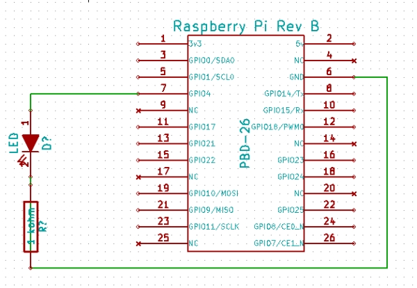
Scope:
To use the Raspberry Pi’s GPIO Pins to turn an LED on and off, and to introduce the basic GPIO functionality of the pi.
BOM:
– 1 raspberry pi (I’m using rev B) with Raspbian OS installed
– 1 LED
– 1 1kohm current limiting resistor
– Breadboard
– Hookup wire
Instructions:
– Build the example circuit on a breadboard, connecting the long leg of the LED to GPIO Pin 7, the short leg of the LED to one leg of the resistor. The other end of the resistor will be connected to GPIO pin 6 (GND)
– Download the example python script (Rpi.GPIO may need to also be installed)
– From a terminal on your raspberry pi, navigate to the directory with the python script and run the following command
"sudo python blink.py"
Note: the script must be ran as superuser to allow control of the GPIO pins
– The LED should now turn on!
Code:
/****************************************************************************** * main.s * by Alex Chadwick * * A sample assembly code implementation of the ok02 operating system, that * simply turns the OK LED on and off repeatedly. * Changes since OK01 are marked with NEW. ******************************************************************************/ /* * .section is a directive to our assembler telling it to place this code first. * .globl is a directive to our assembler, that tells it to export this symbol * to the elf file. Convention dictates that the symbol _start is used for the * entry point, so this all has the net effect of setting the entry point here. * Ultimately, this is useless as the elf itself is not used in the final * result, and so the entry point really doesn't matter, but it aids clarity, * allows simulators to run the elf, and also stops us getting a linker warning * about having no entry point. */ .section .init .globl _start _start: /* * This command loads the physical address of the GPIO region into r0. */ ldr r0,=0x20200000 /* * Our register use is as follows: * r0=0x20200000 the address of the GPIO region. * r1=0x00040000 a number with bits 18-20 set to 001 to put into the GPIO * function select to enable output to GPIO 16. * then * r1=0x00010000 a number with bit 16 high, so we can communicate with GPIO 16. * r2=0x003F0000 a number that will take a noticeable duration for the processor * to decrement to 0, allowing us to create a delay. */ mov r1,#1 lsl r1,#18 /* * Set the GPIO function select. */ str r1,[r0,#4] /* * Set the 16th bit of r1. */ mov r1,#1 lsl r1,#16 /* NEW * Label the next line loop$ for the infinite looping */ loop$: /* * Set GPIO 16 to low, causing the LED to turn on. */ str r1,[r0,#40] /* NEW * Now, to create a delay, we busy the processor on a pointless quest to * decrement the number 0x3F0000 to 0! */ mov r2,#0x3F0000 wait1$: sub r2,#1 cmp r2,#0 bne wait1$ /* NEW * Set GPIO 16 to high, causing the LED to turn off. */ str r1,[r0,#28] /* NEW * Wait once more. */ mov r2,#0x3F0000 wait2$: sub r2,#1 cmp r2,#0 bne wait2$ /* * Loop over this process forevermore */ b loop$ |
For more detail: Using the Raspberry Pi’s GPIO Pins to Drive an LED

