This instructable describes how to realize a solar-powered embedded system for real-time audio signal processing. Based on a Raspberry Pi Zero 2 W, the system is very portable and flexible. It features a dedicated sound card, a two channels 5W amplifier and a MEMS microphone in a 150 mm x 116 mm IP66 waterproof box. A combination of custom hardware and software makes the system energetically autonomous, waking it suitable for unsupervised outdoor installations. A low cost loudspeaker is also realized, with custom enclosure for a Dynavox Minibass PS-138. The first version of the system was originally developed for Klangnetze (2022), a collaborative sound art project for public spaces in Styria, Austria.
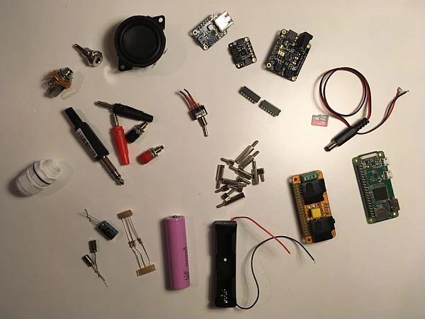
Supplies
Power cycling circuit components:
- 2 x SN74HC02 Quadruple 2-Input Positive-NOR Gates
- 1 x NE555P IC
- 3 x 100k resistors
- 2 x 100u capacitors
- 1 x 0.1u capacitor
- 1 x 2200u capacitor
- 2 x 2.5W/5V 500mAh solar panels
- Adafruit LC709203F LiPoly / LiIon Fuel Gauge and Battery Monitor
- Adafruit PowerBoost 500 Basic
- Adafruit Solar Charger BQ24074
- Male and female pin connectors
- 18650 Li-Ionen battery
- Battery holder
- Two-way switch
- DC socket
Raspberry Pi components:
- Raspberry Pi Zero 2 W
- Raspiaudio MIC+ V2
- 8 GB SD card
Loudspeaker components:
- Dynavox Minibass PS-138
- Stereo jack socket
- Stereo jack plug
- Banana sockets
- Banana plugs
- MDF
Waterproof enclosure:
Step 1: About the System
This is a detailed guide to make an autonomous, solar-powered embedded system for real-time audio signal processing. The project is relatively complex, as it involves several hardware and software components that need to work altogether. This instructables describes how to realize the loudspeaker and the waterproof box containing all the electronics.
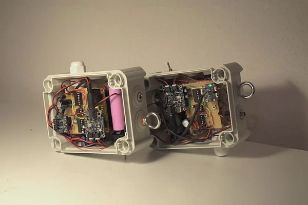
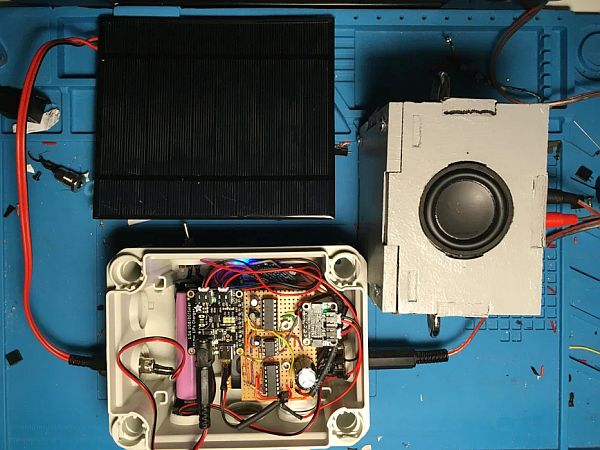
Step 2: What's in the Box
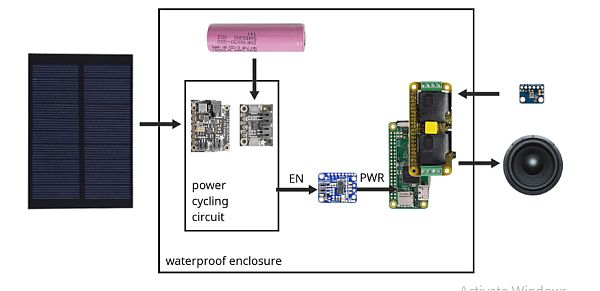
The waterproof box contains a Raspberry Pi Zero 2W, a Raspiaudio MIC+ audio shield, a boost converter, a 18650 battery and battery holder and the power cycling circuit.
Step 3: Power Cycling Logic
The power cycling circuit implements a double logic to make the Pi power on and off autonomously. This is realized by turning on and off the booster, which powers the Pi, according to sunlight conditions and battery level. In particular: booster turns on only if sun is shining and battery voltage is above 3.9V. Booster turns off either after sunset, or if battery voltage is below 3.9V. Also, booster turns off only after Pi has completed shutdown, to avoid SD card corruption.
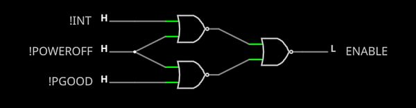
- !INT is the inverted INT pin of the LC709203F. This is HI when battery voltage < 3.9V, LO when above.
- !PGOOD is the inverted PGOOD pin of the BQ24074. This is HI when sunlight hits the solar panel, LO otherwise.
- !POWEROOF is the inverted (active_low) Pi GPIO pin 26 with poweroff overlay enabled. This pulls LO after Pi completes shutdown. It goes back HI after Pi boot.
Step 4: Positive NOR Gates
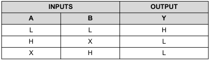
The positive NOR gates will output HI when both inputs are LO, LO in any other case (SN74HC02 datasheet). This means:
- The first NOR outputs HI when battery is below 3.9V (INT == LO) and Pi is shutdown (!POWEROFF == LO).
- The second NOR outputs HI when there is no sun (!PGOOD == LO) and Pi is shutdown (!POWEROFF == HI).
- When either one of these conditions is met, the third NOR outputs LO, turning off the booster. This means the whole system powers off either after sunset, or when battery is below 3.9V (in both cases, after Pi shuts down). To turn the system back on, both !PGOOD and INT need to be HI again. This will cause the first two NOR gates to output LO, and therefore the third NOR gate to output HI, turning on the booster and passing current to the whole system.
The first thing we want to do is to automate Pi shut down according to battery and sun conditions. We therefore need to test hardware communication and write a script that shuts down Pi either when no sun is detected, or when we have low battery.
Step 5: Burn Raspi OS Image
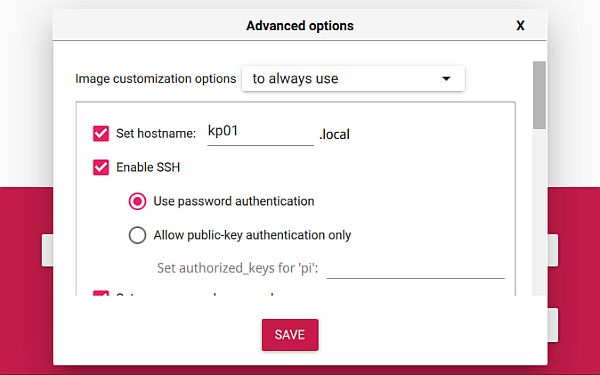
Starting with a fresh new SD card, we first install Raspi OS. This project was built and tested on:
Raspberry Pi OS
- Release date: September 22nd 2022
- System: 32-bit
- Kernel version: 5.15
- Debian version: 11 (bullseye)
Raspberry Pi Imager is a good tool
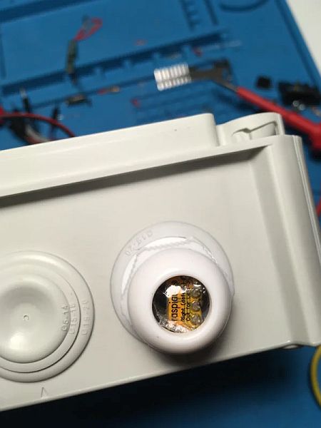
Step 6: Test the Audio Shield
We then want to test that all the main electronics components are working and communicating properly. We start from testing sound. Insert the Rapspiaudio MIC+ Shield in the Raspberry Pi as shown in the picture, then turn it on. Detailed instructions are on the Raspiaudio website.
Once Pi has booted, open a terminal and type:
wget -O - mic.raspiaudio.com | bash
reboot, then:
wget -O - test.raspiaudio.com | bash
Push the onboard button, you should hear “Front Left” “front Right” then the recorded sequence by the microphone.
Step 7: Test I2C Communication (LC709203F ~ Pi)
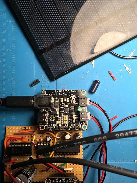
In this step we test for I2C communication between the LC709203F battery monitor and the Pi. In particular, we want to be able to get the current battery voltage value from the LC709203F, and to set the INT pin on the LC709203F to go LOW at a specific threshold (here 3.9V). As shown in picture:
- Connect board VIN (red wire) to Pi 5V
- Connect board GND (black wire) to PiGND
- Connect board SCL (yellow wire) to PiSCL
- Connect board SDA (blue wire) to PiSDA
- Plug battery into either of the JST battery ports.
Detailed instructions here. Once everything is connected, power on the Pi, then:
Install the LC709203 library.
pip3 install adafruit-circuitpython-lc709203f
Slow down the I2C clock as described here:
sudo nano /boot/config.txt
At the end of file, add:
# Clock stretching by slowing down to 10KHz
dtparam=i2c_arm=on
dtparam=i2c_arm_baudrate=10000
Test whether the LC709203 is there:
i2cdetect -y 1
You should get something like this:
     0  1  2  3  4  5  6  7  8  9  a  b  c  d  e  f
00:                         -- -- -- 0b -- -- -- --
10: -- -- -- -- -- -- -- -- -- -- -- -- -- -- -- --
20: -- -- -- -- -- -- -- -- -- -- -- -- -- -- -- --
30: -- -- -- -- -- -- -- -- -- -- -- -- -- -- -- --
40: -- -- -- -- -- -- -- -- -- -- -- -- -- -- -- --
50: -- -- -- -- -- -- -- -- -- -- -- -- -- -- -- --
60: -- -- -- -- -- -- -- -- -- -- -- -- -- -- -- --
70: -- -- -- -- -- -- -- --
Test battery monitor:
sudo nano battery.py
Copy and save the following code. This reads battery voltage every second and sets INT pin to go LOW at 3.9V (I2C register 0x14).
import time
import board
from adafruit_lc709203f import LC709203F

sensor = LC709203F(board.I2C())
sensor._write_word(0x14, 3900)

while True:
    print(sensor.cell_voltage)
    time.sleep(1)
Run:
python battery.py
Terminal should now print the battery voltage.
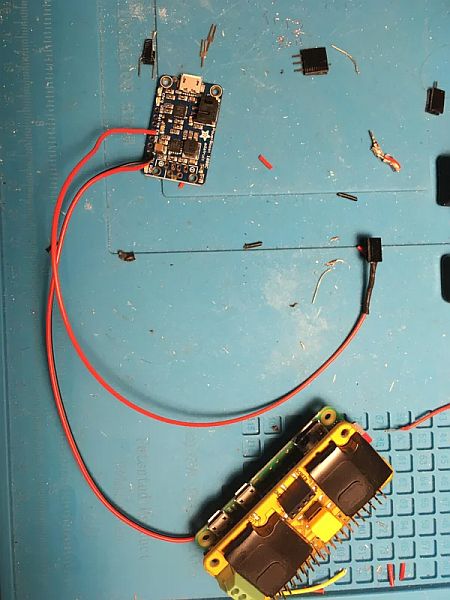
Step 8: Test Solar Charger
Here we want to test whether we can read the state of the solar charger PGOOD pin through the Raspberry Pi GPIO pin 13. The PGOOD pin indicates whether sunlight reaches the solar panel or not. Connect PGOOD to GPIO 13, as shown in picture. Then create the file sun.py:
sudo nano sun.py
Copy and save the following code:
import RPi.GPIO as GPIO
GPIO.setmode(GPIO.BCM)

sun = 13
GPIO.setup(sun, GPIO.IN)

while True:
    if GPIO.input(sun):
        print("no sun")
    else:
        print("sun")
    time.sleep(1)
Run:
python sun.py
Try to hover a light on the solar panel, then move it away. Terminal should print “sun” and “no sun” accordingly.
Step 9: Enable Poweroff Overlay
Enable poweroff overlay. GPIO pin 26 will go LOW at pi shutdown, will be HI after boot. This will be useful to make a graceful automatic shutdown.
sudo nano /boot/config.txt
At the end of file, add:
dtoverlay=gpio-poweroff,active_low
If all tests were successful, we can now make the power cycling circuit.
Step 10: Schematics
- The first QuadNOR (QuadNOR1) is used as an inverter. It inverts the value of PGOOD and INT. All the inputs of the two unused gates are connected to ground.
- The NE555 is set in monostable mode (a.k.a. single shot mode) to de-noise the value of INT at the 3.9V threshold. Specifically, when INT switches from LO to HI at 3.9V, the booster turns on, causing the Pi to boot. This sudden load causes the battery monitor to detect a voltage lower than 3.9V. The INT value therefore goes LO again. Since this happens in a fraction of a second, the Pi finds itself still in a very early boot phase – in particular, GPIO26 will still be LO. With both Pi and INT LO the booster turns off again, causing an infinite boot loop. To avoid this the NE555 IC is set in monostable mode to keep the INT value HI for at least 10 seconds, which is largely enough for the Pi GPIO pin 26 to go HI and complete the boot. The value of R1 and C1 determines how long the output of the NE555 timer will stay HI. Click here to open an online simulation.
- QuadNOR2 performs the logic desribed in step 3.
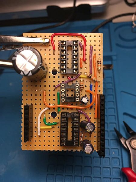
Step 11: Prepare the Perf Board
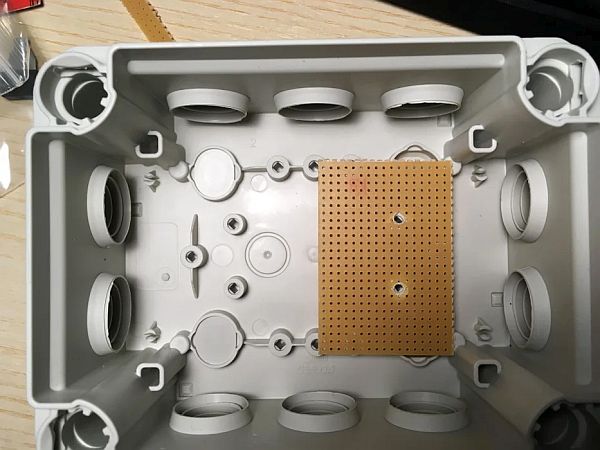
The circuit is built on a small piece of perforated board. Take your enclosure and measure two mounting points, drill holes.
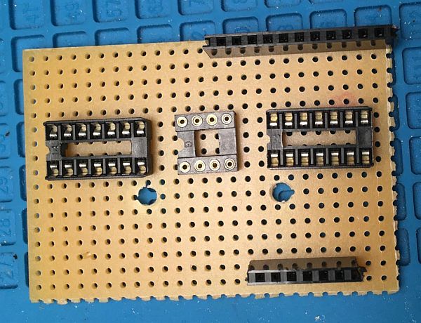
Step 12: Solder Sockets
Step 13: Solder All Caps and Power Rails
Step 14: Complete the Logic
Step 15: Solder Connectors
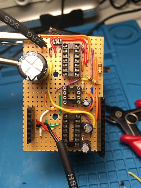
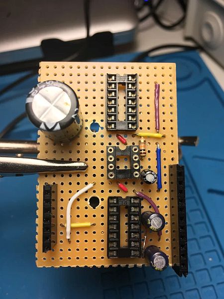
Step 16: Solder Pi and Booster
Step 17: Put It All Together
Insert the solar charger and battery monitor in the sockets. Connect cables to Pi SDA – SCL and to GPIO 13 – 26. Connect booster ENABLE to the power cycling circuit.
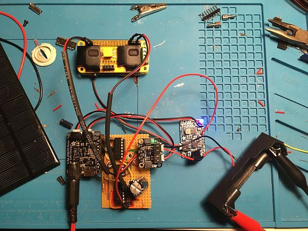
Step 18: Test
Test the power cycling circuit. Start by providing a current of 4.0V and hover a light relatively close to the solar panel. Once Pi boots, run sun.py. Move the lamp away from the solar panel and check that terminal prints “no sun”. Move the lamp back on the panel and check that terminal prints “sun”. Now run battery.py and check that you get correct voltage printed (~4V). Now turn down the voltage from your power supplier to a value below 3.9V, and shut down your Pi manually. Pi should shutdown, followed by booster turning off. Now turn up your power supply to exactly 3.9V. Booster should turn on and Pi should boot. Move away the lamp from the solar panel and shut down Pi manually. Pi should shutdown, followed by booster turning off.
If test succeded, the circuit is working properly. We can now mount everything in the waterproof enclosure.
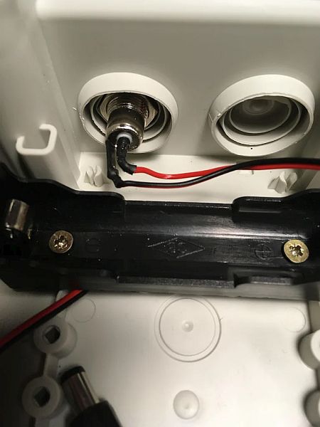
Step 19: Battery Holder
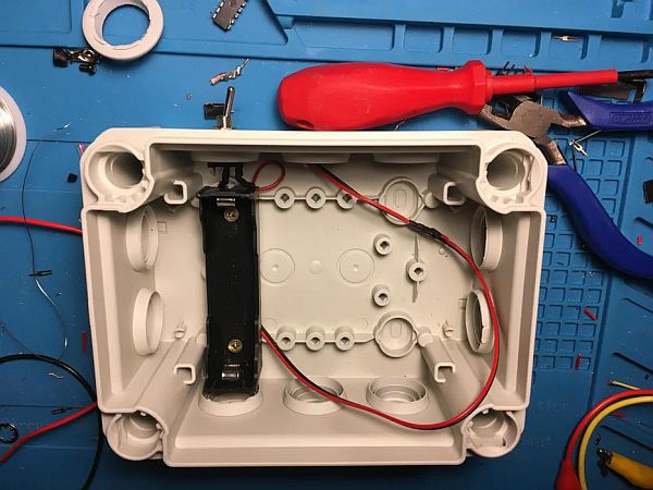
Step 20: DC Plug and Power Switch
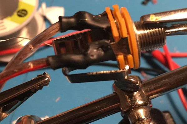
Step 21: Jack Plug