
An Ikea hack that transforms any surface into an ambient, smart interface using Raspberry Pi, a laser projector, and Android Things.
Introduction
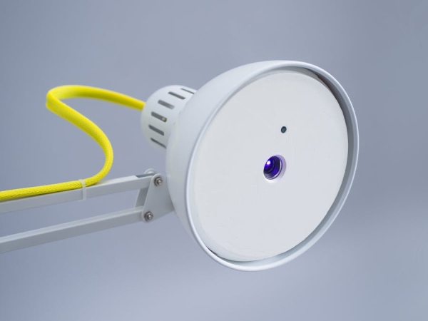
Lantern combines an Ikea lamp, laser projector and Android Things to create a connected projector that explores the relationships between surfaces and content.
It is built around the concept of ‘channels’ – mini apps that can be configured through the companion app, connect to data feeds online and display a projected UI.
Here are some channels we made:
Rather than insisting that every object in our home and office become ‘smart', Lantern imagines a future where projections are used to present ambient, relevant UI around everyday objects. And, as opposed to a screen, when they're no longer needed, the projected UI simply fades away.
At the heart of Lantern is Android Things, a new operating system from Google, designed for embedded devices and the Internet of Things. Android Things makes it way easier to write software for connected devices, especially for mobile developers that are already familiar with Android!
The build
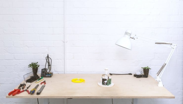
Lantern is built as an Ikea hack using the IKEA Tertial lamp, off-the-shelf parts, a 3D-printed enclosure and our open-source software.
Don't worry If you've never used Android Things before. We'll walk you through the process to get up and running in no time.
Check out the parts list below – once you've printed the housing and have all the parts, it should be about a 60 minute build from start to finish.
Mechanics
- (1x) IKEA Tertial Lamp US | UK
- (1x) 10mm x 2m Braided cable sheath US | UK
- (4x) Cable ties US | UK
- (6x) M2 x 4mm Self tapping screws US | UK
- (3x) M2.2 x 8mm Self tapping screws US | UK
- (5x) M3 x 20mm Self tapping screws US | UK
- (2x) M4 8mm Thumb screws US | UK
- (2x) M4 10mm Threaded inserts US | UK
Electronics
- (1x) UO Smart Beam Projector US | UK
- (1x) Raspberry Pi 3 Model B US | UK
- (1x) Raspberry Pi V2 Camera (optional) US | UK
- (1x) Adafruit ADXL345 accelerometer US | UK
- (4x) Female to female jumper cables (75mm) US | UK
- (1x) MicroSD card (greater than 2GB) US | UK
- (1x) Right-angle Micro-HDMI to HDMI US | UK
- (2x) Right-angle (down) Micro-USB extension cable US | UK
- (2x) Anker Powerline Micro-USB 6ft cable US | UK
- (1x) Anker 2-Port USB power adapter US | UK
Tools you’ll need
- Screwdriver (cross-head, types PH1, PH0)
- Rasp file (+Vice optional)
- Protractor or digital angle ruler
- Rough sandpaper ~80 grit
- Soldering iron + solder (knife head optional)
- Snips (for cutting lamp wire, cable ties)
- Hex key 4 (for lamp grub screw + inserts size 4)
- Small pointy thing like bradawl or screwdriver to undo bulb clips
Chapter 1: Lamp Preparation
1. Remove the cable
First, we will remove the power cord from the lamp. Loosen the screws on the side and then cut the cord near the lamp head. Pull it out through the metal arms.
2. Remove bulb attachment
Using a hex key, remove the screw holding the cable in place.
Insert a small screwdriver through the side of the lamp head. Gently pry the plastic tabs to free the socket. It may be a bit tricky to get it loose.
Turn the lamp head over and remove the plastic screw holding the socket in place. You can now remove the socket.
3. Modding the lamp arm
Unscrew the lamp head from the arm and remove the plastic clip at the end.
File the corner down to a round ‘quarter-circle' radius.
4. Clip the arrow head
Unscrew the lamp head from the arm. Remove all parts from the metal extension.
File the edges of the metal clip so they all are smooth and parallel.
5. File plastic spacer
Take the plastic spacer that was removed with the metal extension. Using sandpaper, file it down to approximately 4.5 mm on both ends.
Filing down the plastic piece will allow the clamp to grip the metal better. This will prevent the head slipping over time.
6. Tighten those screws
Tighten all the screws on the lamp so it’s nice and stiff to move around.
Chapter 2: 3D printing the enclosure
1. Measure your lamp angle
Each lamp is different so the CAD model will need to be adjusted. Using a protractor or a digital angle ruler, measure the angle between the dimples and the lamp arm.
2. Get the CAD
Open the CAD model in OnShape (free for open source projects). It’s a public document so make a copy for you to adjust.
3. Adjust the CAD
Click the Sketch titled ‘EDIT THIS – arm pilot holes’. Select the measurement highlighted above and change the number to the angle you measured in Step 1. This will rotate the features accordingly.
4. Export your model
For each of the three parts, right click on the part name and click Export. Use the following settings:
- Format: STL
- STL format: Binary
- Units: Millimeter
- Resolution: Fine
- Options: Download
5. Print it
Print out the files using a 3D printer. We used an Ultimaker 2+, but feel free to use whatever 3D printer you have access to.
You can also use a 3D-printing service like Shapeways or iMaterialise. Just upload the STL files and they’ll ship ‘em right to your door.
Our Ultimaker 2+ settings:
- Material: PLA
- Nozzle: 0.4mm
Use the default settings but adjust:
- add brim of 10mm
- Nozzle temp for first layer 200°C
- Nozzle temp for rest of print 210°C
- When printing the Top parts (cap and arm) set a wall thickness of 3mm.
Chapter 3: Assemble the hardware
1. Solder the accelerometer
Solder a row of 9 header pins on to the accelerometer. Make sure they extend out the front of the board.
Source: Android Things Lantern