
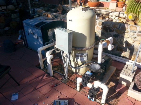
We bought a home with a pool. The first couple of weeks we made several costly mistakes including using the heater to heat the entire pool over 90 degrees. I think we paid $250 for gas that month. We also accidentally drained the spa into the pool.
The solar water heater did have an automation system, and 1 actuator which would turn the solar heat on (start pumping water up to the roof) if the air temperature was 8 degrees warmer than the pool water. The pump was an old 1 hp single speed pump and it needed to be replaced. What I needed to solve for is:
The adults like to use the spa in the evening, while the kids play in the pool during the day. Switching from pool to spa requires rotating 2 values, setting the heater temperature and starting the heaterThe pump needs to run at a higher speed if the pool cleaner is runningThe pump needs to run at a higher speed if the solar heater is onThe pump needs to run at a lower speed when only in a filter/skimmer cycle
Step 1: Pump and Actuators
Installing the new pump should have been simple. Disconnect the old pump, put in the new, but no, new pump needed more clearance for the pump controller, had to reroute the plumbing from the pump to the filter.
I needed to add 3 new actuators:
- Suction valve
- Output valve
- Cleaner/Skimmer valve
Installing the actuators
- Choose ideal alignment of the actuator
- Align the valve handle in the counter-clockwise position
- Remove the valve handle
- Remove the 4 screws that are required for the actuator to attach to the valve
- Install the 4 longer screws through the holes in the actuator
- Remove the cover from the actuator: 4 screws
- Move the lower cam to point at the left toggle switch, where it would close the circuit when the actuator rotates to that position
- Replace the handle by aligning the small slot on the handle with the small slot on the shaft
- Push the shaft in to disengage the gear train, rotate the shaft to the clockwise position
- Move the upper cam to point at the right toggle switch, where it would close the circuit when the actuator rotates to that position
- Remove the handle
- Replace the cover: 4 screws
- Replace the handle and the locking screw

Step 2: Pool controller
- Solder the ‘Arduino Stackable Header Kit – R3' and 3 rows, 16 each row of ‘Break Away Headers – Straight' to the ‘Mux Shield II' (Mux Shield). Put in the solder jumpers to make row 1 digital output, row 2 digital input, row 3 analog input
- Connect Mux Shield to the ‘Arduino Uno – R3' (Arduino)
- Assemble the ‘Raspberry Pi Complete Starter Kit — [Model B – 512 MB]' (RPi) and make sure it boots. The wifi adapter doesn't have enough range to connect from outside, run ‘100' Blue Cat5e Patch Cable' (Network cable) to your router
- Get the RPi on the network and set a static IP address on your router
- sudo apt-get update
- Use ‘Foam PCB Tape – 3M VHB Acrylic' (Foam tape) to attach the Arduino to the top of the RPi
- Connect a short USB cable from RPi to Arduino
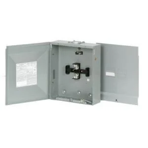
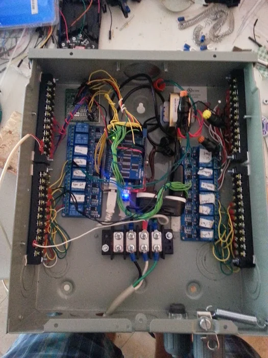
- Use Foam Tape to attach the RPi to the off center left and top of the ‘125 Amp 4-Space 8-Circuit BR Type Mail Lug Loadcenter NEMA 3R' (Electrical box)
- Drill 3/8″ holes in the corners of the ‘Kootek 8 Channel DC 5V Relay Module for Arduino Raspberry Pi DSP AVR PIC ARM' (Relay board)
- Use Foam tape to hold relay board in place, fasten the relay board to the electrical box with a rivet
Step 3: Transformer and terminal blocks
- Drill 3/8″ holes through the holes in the conduit strap and the electrical box spaced evenly at the top of the electrical box
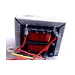
- Use foam tape to hold ‘Philmore 24VAC CT 1A Power Transformer' (Transformer) in place, off center right and top, on the electrical box
- Drill 3/8″ holes through the holes in the transformer and the electrical box and fasten with rivets
- Use foam tape to hold ‘CINCH TERMINAL BLOCKS. CINCH TERMINAL BLOCKS. #6-32 SCREW SIZE. 4-POSITION. 4-140-P' (4 pos terminal block) in place, couple inches from the bottom centered, on the electrical box
- Drill 1/2″ holes through the holes in the 4 pos terminal block and the electrical box and bolt in place
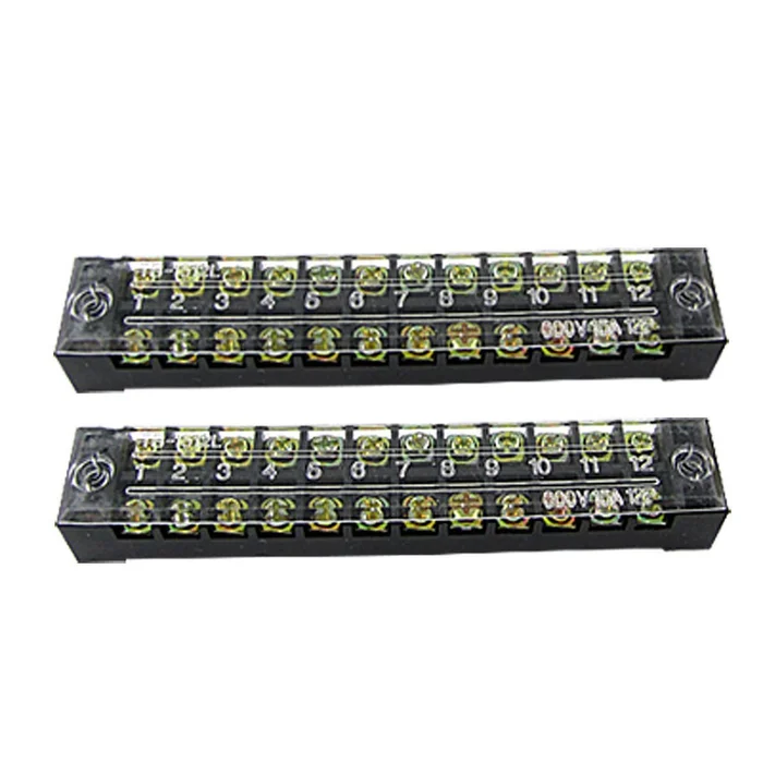
- Use foam tape to hold the ‘2 Pcs 12 Position Covered Barrier Screw Terminal Block 600V 15A' (12 pos terminal block) (4 total) along the side rails
- Drill 1/2″ holes through the 12 pos terminal blocks and bolt in place
Step 4: Thermistors
Can't find a product image of the 10k ohm resistor 5 pack, but I found it at Fry's. I wired for 4 thermistors, but, I'm only using 3. Find a better prototyping board.
Follow these steps for 4 resistors, 4×2 breakaway headers
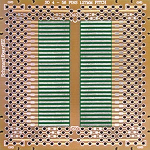
- On a small prototyping board solder 10k ohm resistor to a grounded row (5 connected) and a row with 3 (minimum) through holes
- Solder 2 breakaway headers to connect with the 10k ohm resistor
Then
- Solder 1 breakaway header to the grounded row to connect to gnd
- Solder 5 breakaway headers to a single row all connected for 5v VCC
Set up the thermistor terminal block
- Get 4 black female jumper wires
- Get 4 red female jumper wires
- Cut off 1 end of each of the 8 jumper wires, strip 1/4″ from the end and attach '22 – 16 AWG, #4 – 6 Stud Size Red Vinyl-Insulated Spade Terminals (75-Pack)' (red spade)
- Connect jumper wires to bottom of top left terminal block alternated red and black on positions 1,2,3,4,5,6,7 and 8
- Connect female end of red jumper wire to 4 of the 5v VCC breakaway headers on the prototyping board
- Connect female end of black jumper wire to one of the breakaway headers at each end of the 10k ohm resistor
- Get 4 yellow female jumper wires
- Connect yellow jumper wire to Mux Shield, analog in (row 3) position 0,1,2,3
- Get 1 red female/male jumper wire
- Connect red jumper wire from the last 5v VCC breakaway header to 5v on the Mux Shield
- Get 1 black female/male jumper wire
- Connect black jumper wire from the gnd breakaway header to the gnd on the MuxShield
- Hang extra wiring on conduit straps at the top of the electrical box
Step 5: Heater, Lights internals
I have a dream of adding landscaping lighting to this system, so there are a couple of extra steps here, maybe you already have them.
Heater
I destroyed relay board position 1 when I drilled for the rivet in the corner, so these instructions start on position 2. If you start on position 1, you will have some small code changes at the end of the day.
- Get 4 white 14 guage wires
- Strip 1/4″ from both sides of each wire
- Connect '16 – 14 AWG #4-6 Stud Size Blue Vinyl-Insulated Spade Terminals (75-Pack)' (blue spade) to 1 end of each of 4 wires
- Connect 4 blue spade ends to bottom left 12 pos terminal block positions 1,2,3,4
- Connect bare end of 4 wires to terminals on left relay board in positions 2 and 3
Water Lights
- Get 2 yellow 14 guage wires
- Get 2 green 14 guage wires
- Strip 1/4″ from both sides of each wire
- Connect blue spade to 1 end of each of 4 wires
- Alternating green and yellow, attach blue spade ends to bottom left 12 pos terminal block positions 5,6 and 7,8
- Alternating green and yellow, Connect bare end of 4 wires to terminals on left relay board in positions 4 and 5
Yard Lights
- Get 2 yellow 18 guage wires
- Get 2 black 18 gauate wires (these need to be fairly long, they connect to transformer for 24v)
- Connect red spade to 1 end of each of 4 wires
- Get 2 green 18 guage wires (these need to be fairly long, they connect to transformer for 24v)
- In order black, yellow, black, yellow connect red spade ends to bottom left 12 pos terminal block positions 9,10,11,12
- In order green, yellow, green, yellow connect bare end of 4 wires to terminal on left relay board positions 6 and 7
- Run bare end of green and black wires to each red output wire on the transformer
Step 6: Actuators and Pump internals
Actuators
- Get 4 red 18 guage wires
- Get 4 white 18 guage wires
- Get 4 black 18 guage wires
- Get 4 green 18 guage wires
- Strip 1/4″ from both sides of each wire
- Connect red spade to 1 end of each of 12 red, white, black wires
- Alternating red, black and white, attach red spade ends to top right 12 pos terminal block positions 1,2,3,4,5,6,7,8,9,10,11,12
- Connect bare end of black wires to 1 end of transformer
- Connect bare end of green wires to other end of transformer
- Alternating red, green and white, connect bare end of 12 wires to terminals on right relay board in positions 1,2,3 and 4
- Hang extra wiring on conduit straps at the top of the electrical box
Pump
- Get 4 green 18 guage wires
- Get 4 yellow 18 guage wires
- Strip 1/4″ from both sides of each wire
- Connect red spade to 1 end of each of 8 wires
- Alternating green and yellow, attach red spade ends to bottom right 12 pos terminal block positions 1,2,3,4,5,6,7,8
- Alternating green and yellow, connect bare end of 8 wires to terminals on right relay board in positions 5,6,7 and 8
Step 7: Power
- Get a standard 110V outlet
- Get 14 guage black wire
- Get 14 guage white wire
- Get 14 guage green wire
- Attach ‘6 AWG, 3/8 in. Blue Vinyl-Insulated Ring Terminals (4-Pack)' (blue ring) to 1 end of each of 3 wires
- Attach blue spade to 1 end of each of 3 wires
- Connect blue spade end of black wire to outlet live/main connection
- Connect blue spade end of white wire to outlet neutral connection
- Connect blue spade end green wire to outlet ground connection
- Connect blue ring end of black wire to 4 pos terminal block at pos 2
- Connect blue ring end of white wire to 4 pos terminal block at pos 3
- Connect blue ring end of green wire to 4 pos terminal block at pos 4
- Cut a plug off of the end of an extension cord or something that you no longer need
- Connect black and white wires from this plug to transformer and secure with wire nuts
- Plug in this plug to the new internal outlet
- Plug in a wall wart (had to find a smaller one than the one that came with the RPi) to the new internal outlet
- Plug in the usb cable to the wall wart
- Plug in the usb cable to the RPi
Heater power
- Get 2 14 guage white wires
- Attach blue ring to 1 end of each of 2 wires
- Attach blue spade to 1 end of each of 2 wires
- Connect blue ring ends to 4 pos terminal block at pos 1 and 2
- Connect blue spade ends to top side of the bottom left 12 pos terminal block at pos 2 and 4
Step 8: Water lights
- Shut off the breaker for the pool and spa light switches
- At the top of the light switch box, there should be some sort of electrical connection box. Open this box
- Get 2 14 guage yellow wires (long enough to go from light switch into electrical box)
- Get 2 14 guage blue wires (long enough to go from light switch into electrical box)
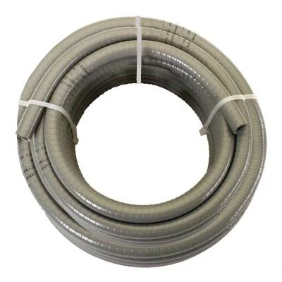
- Get conduit, and liquid tight connectors (long enough to go from light switch into electrical box)
- Disconnect the black wire (main/load) from each switch, note which black connects to which switch
- Connect yellow wire to breaker side of each switch attach with orange wire nut
- Connect blue wire to switch side of the main/load connection, attach with orange wire nut
- Run all 4 wires through knock out of electrical box, then through Liquid Tight connector, and through conduit
- Screw liquid tight connector through knock out on electrical box
- Push conduit into liquid tight connector and screw down
- Close the electrical box
Step 9: Get the Externals in Place
- Run thermistor wires through a knock out hole on the electrical box (found plastic pass-throughs at home depot, but can't find them online)
- Connect thermistors to top side of the top left 12 pos terminal block positions 1,2,3,4,5 and 6
- Run heater wires through a (should be in a conduit with liquid tight connector already) knock out hole on the electrical box
- Connect 2 red wires to top side of bottom left 12 pos terminal block positions 1 and 3
- Run water light wires through a liquid tight connector and knock out hole on the electrical box
- Connect spa light wires to top side of bottom left 12 pos terminal block positions 5 and 6
- Connect pool light wires to top side of bottom left 12 pos terminal block positions 7 and 8
- Run actuator wires through a knock out hole on the electrical box
- Connect actuator wires to top side of the top right 12 pos terminal block positions 1,2,3,4,5,6,7,8,9,10,11 and 12
- Run pump relay wires through 90 degree slip liquid tight connector
- Run pump relay wires through conduit, push conduit on to liquid tight connector and lock in place
- Attach liquid tight connector to knock out on electrical box, run pump relay wires through
- Push conduit on to liquid tight connector and lock in place
- Connect pump relay wires to top side of the bottom right 12 pos terminal block positions 1,2,3,4,5,6,7 and 8
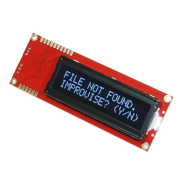
Step 10: LCD Display
- Get 1 red 18 guage male/bare jumper wire. This needs to be very long, ~2′
- Get 1 black 18 guage male/bare jumper wire. This needs to be very long, ~2′
- Get 1 yellow 18 guage male/bare jumper wire. This needs to be very long, ~2′
- Connect the bare end of the red wire to the ‘Serial Enabled 16×2 LCD – White on Black 5V' (LCD display) at the VDD position
- Connect the bare end of the black wire to the LCD display at the GND position
- Connect the bare end of the yellow wire to the LCD display at the RX position
- Connect the male end of the red wire to the
- Connect the male end of the black wire to a gnd connection on the Arduino
- Connect the male end of the yellow wire to the Arduino on digital input pin 3
Step 11: Arduino Sketch
The sketch was getting very long and confusing, so I broke it out into a bunch of libraries.
MyRelay – Use to set the state of a relay
MyButton – Use to get the state of a button. Includes debounce code
MyThermistor – Use to get the temperature
MyControl – Each device uses this library to get the next control code if a button is pressed and holds the variable whether the user has pressed a button, or serial control code has been sent
There are then libraries for each control type (Flow, Pump, Heat, Cleaning, Water Lights, Yard Lights, Temperatures)
Lastly, the sketch itself which reads serial input, reads user button presses, waits a couple of seconds, and does whatever the user has requested and controls the LCD.
Now you can test your sketch from the Arduino IDE's Serial Monitor by sending commands like ‘0700' to get the air temperature
Attachments

Step 12: Command Server
Raspberry Pi and Arduino talk over serial, but every serial connection restarts the Arduino. So, I wrote a Serial command server that starts at RPi boot. It starts at boot, but I'll check its status every minute via cron. The command server only answers localhost, so it shouldn't be hackable. This step requires installation of pySerial.
https://pypi.python.org/pypi/pyserial
Download, unzip, cd pyserial*, exec `sudo python setup.py install`
- Put command_server in /etc/init.d/
- Put command_server.py in /usr/local/bin/
- Put test_server.py in /home/pi/
- sudo chmod 755 /etc/init.d/command_server
- sudo chmod 755 /usr/local/bin/command_server.py
- sudo chmod 755 /home/pi/test_server.py
- sudo update-rc.d command_server defaults
- cd ~
- ./test_server.py
- Command To Send: 0700
- You should see the air temperature
Attachments
Step 13: Set Status From Schedule and Persistent Command Storage
I ran into too many failures with the Arduino. It holds state, but the state on digital out is not readable. My concern was what could happen if a scheduled update is missed, so every minute I am pushing what the Arduino should be doing.
Step 14: Delete