
Raspberry Pi is a popular board based on the ARM architecture, specifically designed for electronic engineers and hobbyists. It has gained a strong reputation as a reliable platform for project development. With its increased processor speed and 1 GB RAM, Raspberry Pi can be utilized in a wide range of high-profile projects, including image processing and Internet of Things (IoT) applications.
To embark on such projects, it is crucial to have a solid understanding of the basic functionalities of Raspberry Pi. In this tutorial series, we will cover all the fundamental aspects of Raspberry Pi, discussing one function in each tutorial. By the end of this series, you will possess the necessary knowledge and skills to independently tackle high-profile projects. You can refer to the “Getting Started with Raspberry Pi” and “Raspberry Pi Configuration” tutorials for initial guidance.
In previous tutorials, we have explored LED blinking, button interfacing, and PWM (Pulse Width Modulation) generation. In this particular tutorial, we will focus on controlling the speed of a DC motor using Raspberry Pi and the PWM technique. PWM allows us to achieve variable voltage output from a constant power source, as we discussed in the previous tutorial.
Raspberry Pi 2 is equipped with 40 GPIO (General Purpose Input/Output) pins. However, only 26 of these GPIO pins (GPIO2 to GPIO27) are programmable, as some pins serve special functions. Excluding these special GPIO pins, we have 17 GPIO pins available for general-purpose use. For further information about GPIO pins, you can refer to the tutorial titled “LED Blinking with Raspberry Pi.”

Each of the 17 GPIO pins available on Raspberry Pi is capable of delivering a maximum current of 15mA. It's important to note that the total current drawn from all GPIO pins combined should not exceed 50mA. This means that on average, we should not exceed 3mA per GPIO pin. It is crucial to exercise caution and have a clear understanding of what you're doing when working with these pins.
The Raspberry Pi board also provides +5V (Pin 2 & 4) and +3.3V (Pin 1 & 17) power output pins for connecting external modules and sensors. It's important to remember that these power rails are connected in parallel to the processor's power. Drawing high current from these power rails can have an impact on the processor. The Raspberry Pi board incorporates a fuse that will trip if a high load is applied. It is safe to draw up to 100mA from the +3.3V rail. It's worth mentioning this because we will be connecting a DC motor to the +3.3V rail. Considering the power limitations, it is advisable to connect low-power motors to this rail. If you intend to drive a high-power motor, it is recommended to power it from a separate power source.
Components Required:
For this project, we are utilizing the Raspberry Pi 2 Model B running on the Raspbian Jessie operating system. As for the hardware requirements, we have discussed them previously, which you can refer to in the Raspberry Pi Introduction. In addition to those requirements, we will need the following components:
– Connecting pins
– 220Ω or 1KΩ resistors (3)
– Small DC motor
– Buttons (2)
– 2N2222 transistor
– 1N4007 diode
– Capacitor – 1000uF
– Breadboard
These components are essential for the successful implementation of the project.
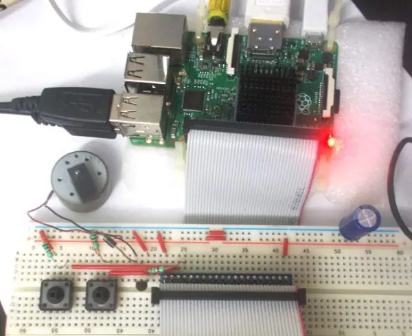
Circuit Explanation:
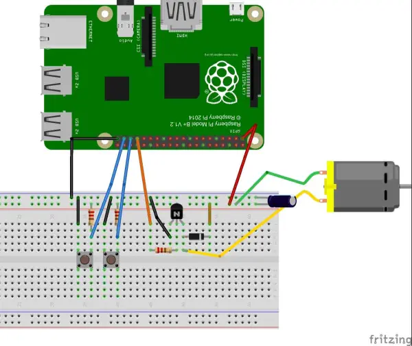
As mentioned earlier, since we cannot draw more than 15mA from any GPIO pin, directly connecting the DC motor to the Raspberry Pi for speed control is not feasible, as the motor requires more than 15mA. Doing so may lead to permanent damage to the board.
To overcome this limitation, we will employ an NPN transistor (2N2222) as a switching device. The transistor will drive the high-power DC motor by receiving the PWM signal from the Raspberry Pi. It is important to note that connecting the transistor incorrectly can impose a heavy load on the board, so caution must be exercised during the connection process.
Since the motor is an induction motor, switching it on and off generates inductive spiking. This can result in significant heating of the transistor. To protect the transistor against inductive spiking, we will use a diode (1N4007) in the circuit.
Additionally, to reduce voltage fluctuations, we will connect a 1000uF capacitor across the power supply, as depicted in the circuit diagram. This capacitor will help stabilize the power supply and ensure smoother motor operation.
Working Explanation:
After ensuring that all the connections have been made according to the circuit diagram, you can power on the Raspberry Pi to begin writing the program in Python.
In the Python program, we will be utilizing a few commands. First, we need to import the GPIO file from the library. This file allows us to program the GPIO pins of the Raspberry Pi. Additionally, we will rename “GPIO” to “IO” for convenience. This means that whenever we refer to the GPIO pins in the program, we will use the word “IO” instead.
import RPi.GPIO as IO
Occasionally, when attempting to use certain GPIO pins, they may already be assigned to other functions, resulting in warning messages during program execution. To bypass these warnings and allow the program to proceed, we can use the following command, which instructs the Raspberry Pi to disregard the warnings:
IO.setwarnings(False)
When referring to the GPIO pins of the Raspberry Pi, there are two options. We can either use the pin numbers as labeled on the board (e.g., “PIN 35”) or use their corresponding function numbers (e.g., “GPIO19”). In our program, we need to specify whether we will be representing the pins using the board pin numbers or the function numbers.
IO.setmode (IO.BCM)
We are setting GPIO19 (or PIN35) as output pin. We will get PWM output from this pin.
IO.setup(19,IO.IN)
After setting the pin as output we need to setup the pin as PWM output pin,
p = IO.PWM(output channel , frequency of PWM signal)
The aforementioned command serves two purposes: setting up the channel for PWM output and defining the frequency of the PWM signal. In this case, the variable ‘p' is used as a placeholder, but it can be named differently as desired. GPIO19 is selected as the PWM output channel, and a frequency of 100 has been chosen, as we do not want to observe LED blinking.
The subsequent command is used to initiate the generation of the PWM signal. ‘DUTYCYCLE' refers to the duty cycle, which determines the ON time of the signal. A value of 0 means the LED will be ON for 0% of the time, while 30 means the LED will be ON for 30% of the time. A value of 100 indicates that the LED will be constantly ON.
The ‘p.start(DUTYCYCLE)' command starts the PWM signal generation with the specified duty cycle.
Within the if statement, if the condition within the parentheses is true (GPIO pin 26 goes low), the statements inside the loop will be executed once. Conversely, if the GPIO pin 26 does not go low, the statements inside the loop will not be executed.
if(IO.input(26) == False):
Once the program is written and executed, the last step is to operate the control. There are two buttons connected to the Raspberry Pi: one for incrementing the duty cycle of the PWM signal and the other for decrementing it. By pressing the appropriate button, the speed of the DC motor can be increased or decreased accordingly. With these controls in place, we have successfully achieved DC motor speed control using Raspberry Pi.
Code
import RPi.GPIO as IO # calling header file which helps us use GPIO’s of PI
import time # calling time to provide delays in program
IO.setwarnings(False) #do not show any warnings
x=0 #integer for storing the duty cycle value
IO.setmode (IO.BCM) #we are programming the GPIO by BCM pin numbers. (PIN35 as‘GPIO19’)
IO.setup(13,IO.OUT) # initialize GPIO13 as an output.
IO.setup(19,IO.IN) # initialize GPIO19 as an input.
IO.setup(26,IO.IN) # initialize GPIO26 as an input.
p = IO.PWM(13,100) #GPIO13 as PWM output, with 100Hz frequency
p.start(0) #generate PWM signal with 0% duty cycle
while 1: #execute loop forever
p.ChangeDutyCycle(x) #change duty cycle for changing the brightness of LED.
if(IO.input(26) == False): #if button1 is pressed
if(x<50):
x=x+1 #increment x by one if x<50
time.sleep(0.2) #sleep for 200ms
if(IO.input(19) == False): #if button2 is pressed
if(x>0):
x=x-1 #decrement x by one if x>0
time.sleep(0.2) #sleep for 200ms