
Simple LED matrix Clock based on the popular ESP8266 with Real Time Clock module and time synchronization over WiFi from an NTP server.
Step 1: Parts and Tools
First let's see what we need.
Parts:
- 6 x 8×8 MAX7219 LED Matrix
- 1 x RTC DS3231
- 1 x ESP12 Board
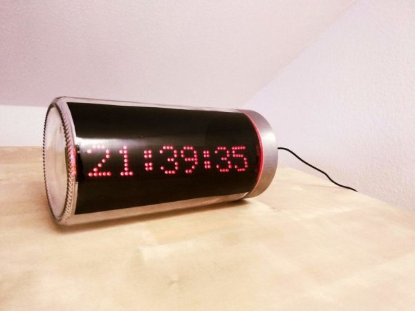
- 1 x pasta jar
- 1 x 5.5mm X 2.1mm DC Power Supply Metal Jack Panel Mount
- 1 x USB to 5.5mm X 2.1mm barrel jack 5v dc power cable
- 1 x Window tint film
- 11 x female to female dupont wires
Tools:
- soldering iron
- spray bottle
- hobby knife
- double sided tape
All the parts can easily be sourced from ebay/aliexpress and/or local stores.
Step 2: Preparing the LED Matrix
I found it easier to buy 2 x 4pcs modules, cut one of them in half and solder it to the other one while maintaining the orientation printed on the PCB.
Step 3: Connect the LED Matrix Display and the RTC to the ESP8266
Solder the pin headers on the modules then use the dupont cables to connect them as follows.
MAX7219 to ESP8266
- VCC – 3.3V
- GND – GND
- CS – D8
- DIN – D7
- CLK – D5
DS3231 to ESP8266
- GND – GND
- VCC – 3.3V
- SDA – D1
- SCL – D2
One note on the RTC module, apparently it also has the ability to charge the battery, however that's not a good idea when using a CR2032. One possible solution would be to cut the trace marked on the image in order to disable the charging part of the circuit. Further information on this can be found here.
Step 4: Flash the ESP8266 Module
Nest step would be to upload the code to the ESP8266.
While the original code can be found here (many thanks to the author !) you can find attached the English version of it.
Read more: ESP8266 LED Matrix Clock