
Have your ever drove out of your garage and after few minutes into your drive, feared you did not close the door?
** What if you did really leave the door open?
The garage door might close itself after few minutes, but that means your home's security has been compromised!
** Did you ever feel the need to check the status of your garage door maybe from your office?
>> This project offers a solution to all those problems!
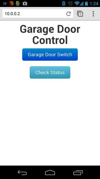
This Raspberry-Pi based Garage door opener is capable of controlling of your garage door which enables you to open/close the door when desired, and lets you monitor the status to report back if the door is opened or closed at that moment.
An intuitive User-Interface lets the user to control and monitor the garage door through the Internet and thus giving access to the door from anywhere in the world!
This instructable article describes the step by step approach.
Step 1: Design Hardware
Step 1: Design hardware that can control and monitor the status of the door.
Things you need:
> A raspberry-Pi, enabled with Wi-Fi (preferably) or ethernet
> single strand wires
> magnets
> A USB power supply of at least 1A output capacity to drive the raspberry-pi
> Things to make the custom PCB listed in the BOM
Check the BOM.txt file attached for the detailed Bill Of Materials
Things I assume you already have or intend to have:
A simple garage door system operated with a remote. Ex: Lift Master
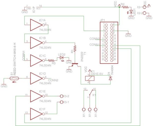
The schematic designed is shown below.
Hover over to see the descriptions for each block.
I used Eagle CAD to design the circuit. Download the .sch for the schematic
Step 2: Make PCB
Next step is to make a PCB from the circuit we designed
I used Eagle CAD to generate the .brd files
Download the .brd file and it is ready to be used!
Step 3: Get the PCB
I got my custom PCB done at OSHpark.com
After i got the PCB, I discovered the board was missing a vital trace route that was driving the relay.
Hover over the Top PCB image to check tweak.
You could make the changes to .brd file itself before sending it out to the fab.
For more detail: Garage door controller using Raspberry-Pi: Monitor status and Control your garage from anywhere in the world!