
A Helium-based air quality sensor and solar setup.As environmental concerns and awareness increase, I decided to build and deploy an array of wireless, self-contained, weather-resistant, solar-powered air quality sensors, also known as WSPAQS.
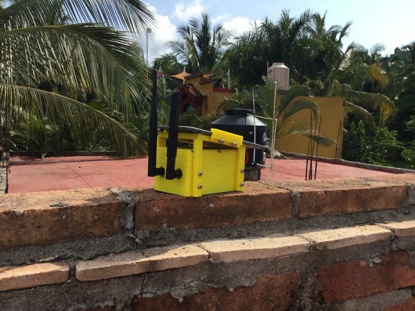
The sensor array measures CO2 levels and VOCs. (What's a VOC, you ask? See below as it's rather long.) It also has a voltage/current sensor to keep track of the solar charge.
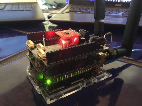
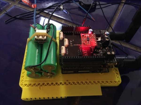
We will be using an Arduino Uno, a Raspberry Pi 3, Helium Starter Kit, my board, an Adafruit 6 volt solar panel a 24 VAC/VDC portable power converter to USB board (design files attached), and a hacked portable battery pack to build an awesome sensor setup that will transmit the data to Librato.
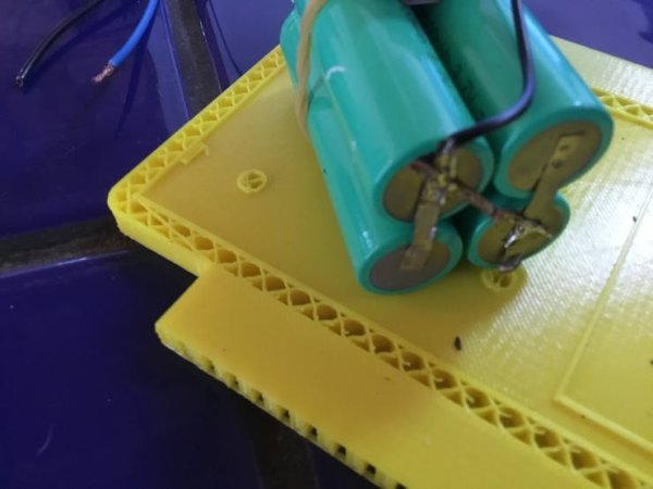
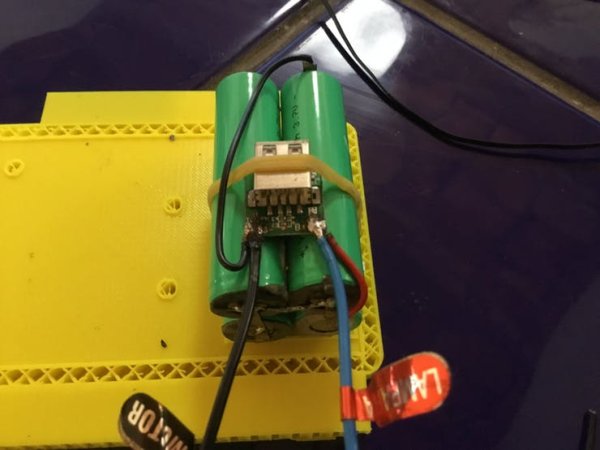
Step 1: Hack apart a battery pack and test it for compatibility witth your system
Step 2: Add solar panel and put it in the sun

Step 3: Modify the battery pack to power the sensor array and so it fits into the box a bit easier
I cut the pack in 2 pieces and re-soldered them together, then soldered 2 wires to the power output for powering the Helium and Arduino sensor board array….the WSPAQS.
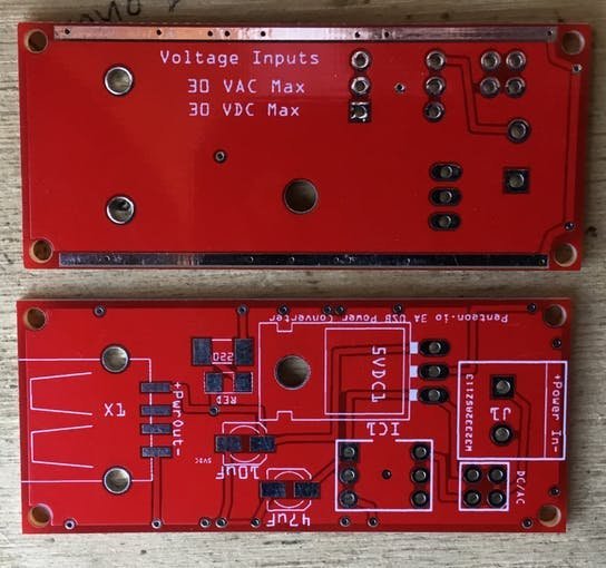
Step 4: Your board
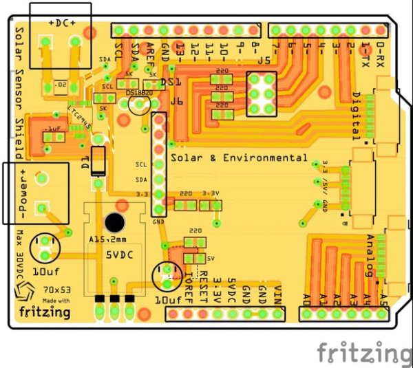
These boards can be ordered through PCBWay: http://pcbway.com. There is a Gerber file in the tutorial that you can upload and pay $5.00. You'll then have it in 7 days.
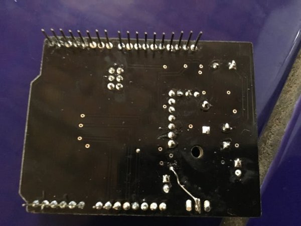
Step 5: Solder your board starting with the SMD parts first
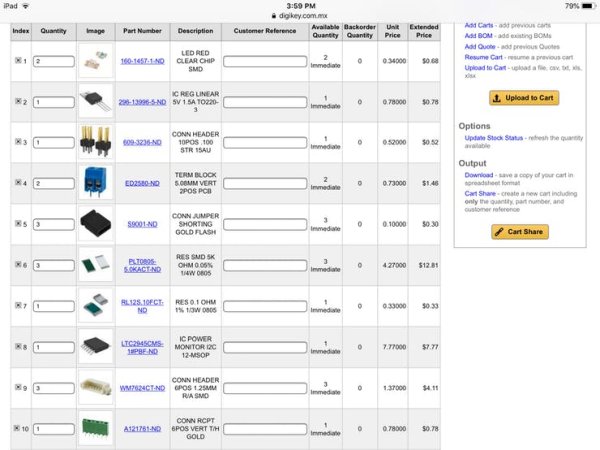
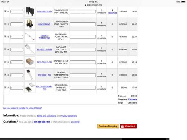
Parts List
http://www.digikey.com.mx/short/j5p41f
The Stackable Arduino pins can be purchased from SparkFun for around $4.
Tip: Buy a good low temperature solder paste… and steal your wife's toaster oven for a while…. There are plenty of tutorials out there on how to solder with reflow paste, It’s really easy you will also need some de-soldering braid to clean up the solder a bit. As well as a good small diameter solder.
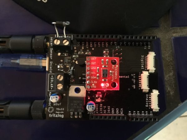
Test your setup
Care should be taken in testing to make sure you don’t burn something out… but luck is on my side and it works flawlessly.
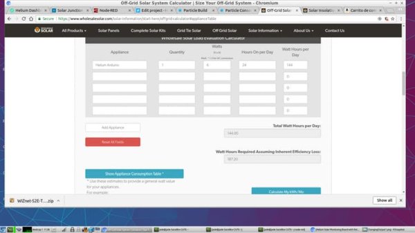
To make this project totally viable and actually for real world
I noticed was that the board needs minimum a solar panel of putting out at least 6 volts under full sun and it has to run for at least 8 hours without sun… If needed a larger battery bank or solar panel would be recommended. I also did some power analytics and found that under full broadcast @ 7 volts DC input, the setup draws .525 to 1 amp with fan running so it's using 144 Watt/hours per day, so you need a minimum setup of 12 Volt 5.2 Watt solar panel. The system wouldn't even start broadcasting until it received 7 VDC. So a minimum battery size would be 12 VDC…
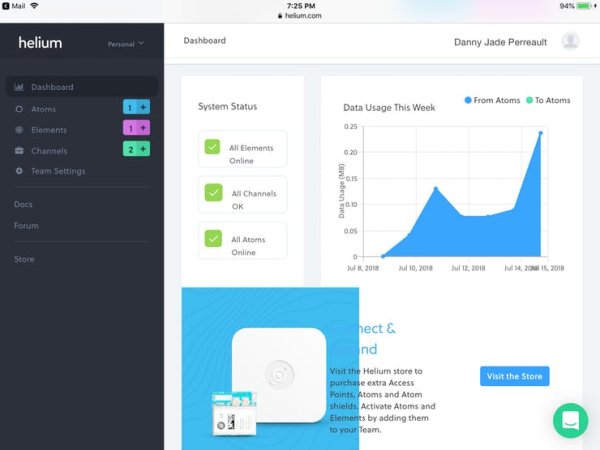
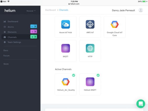
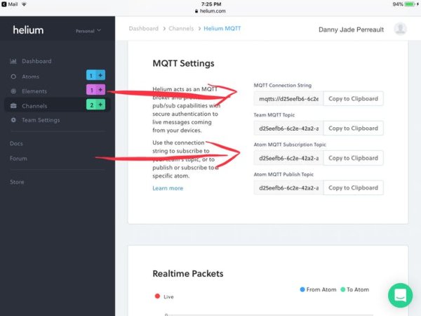
Getting connected to Your helium account

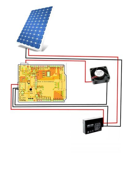
Wiring Diagram
- A charge controller isn't really needed for a lead acid battery when your not pulling huge amps or inputting large voltages the Panel can only put so much into the system ..Your panel should only be large enough to charge the Battery..About 2 to 5 Volts over battery voltage unconnected
- the fan is attached to one side of the voltage sensor in order to accurately measure Amps and volts used..The Board can take 24 VDC max so there is lots of room for capacity.
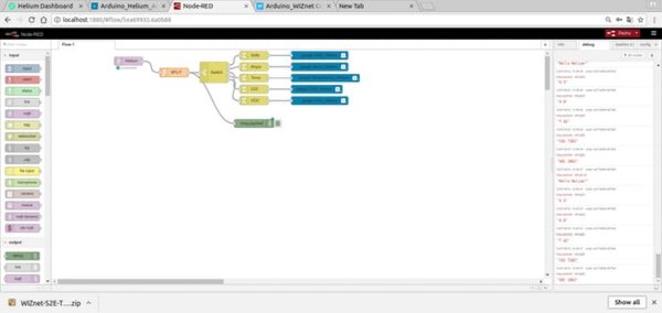
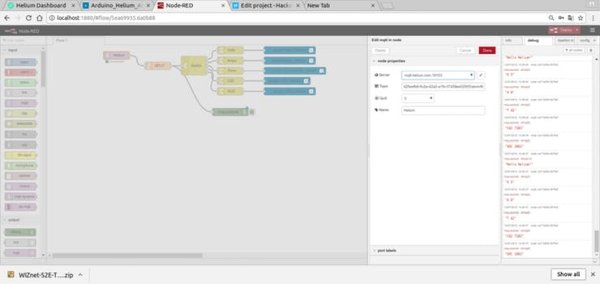
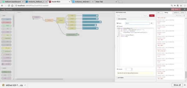
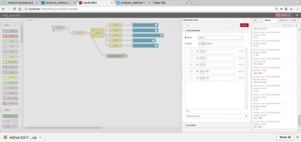
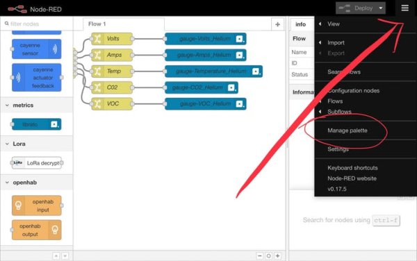
Raspberry Pi Node-RED Programming
I have always said I am definitely not a programmer and design is my forte but here is a simple work around to split you code up and send it to Librato, and as always a picture says a 1,000 words.
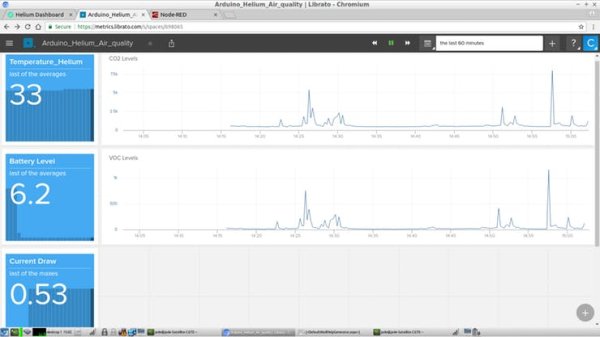
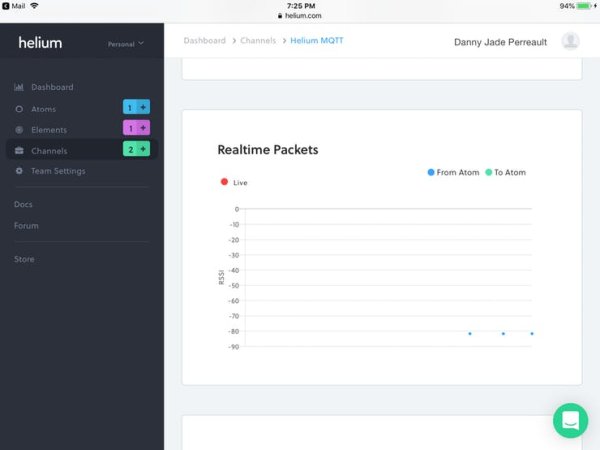
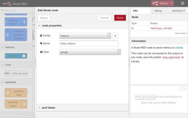
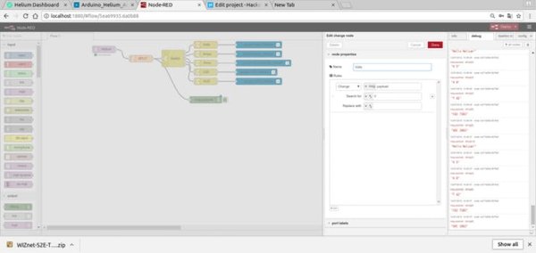
Data Analytics Option 1: Librato and Node-RED
When the data comes out of Helium's MQTT it comes out as a string (V 6 : A 2 :T 30: C02 555: VOC 7293) that has to be separated into separate entities before it goes out to Librato and the V:A:T etc has to be stripped out as well and given a label. So no errors are generated. Node-RED is definitely a solution for this…
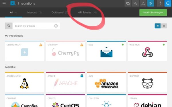
Librato setup is extremely easy. First get an account and follow the pictures.
1. After logging in go to Integrations and click on API Tokens
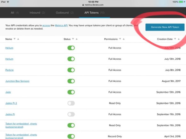
2. In API Tokens click on Generate new API Token
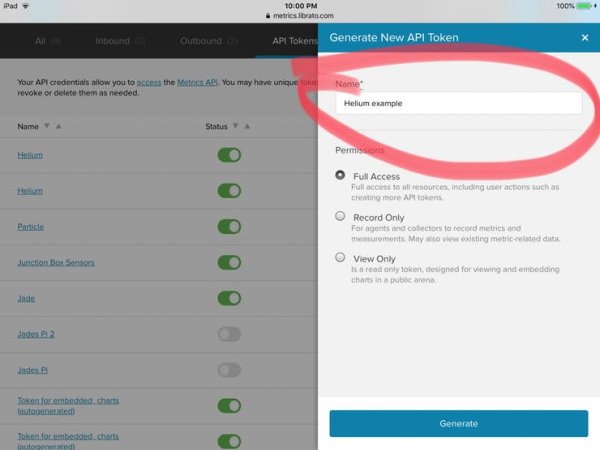
3. Name your integration
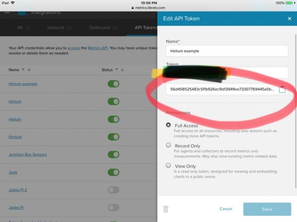
4. Generate your code you will need to copy (CNTL C) the token and make note of the email address above it for the next step.
YOU ARE DONE… STUFF WILL COME OUT OF LIBRATO.
and the Librato output

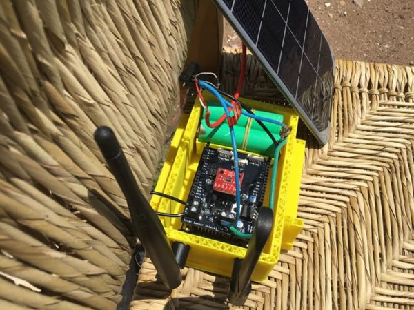
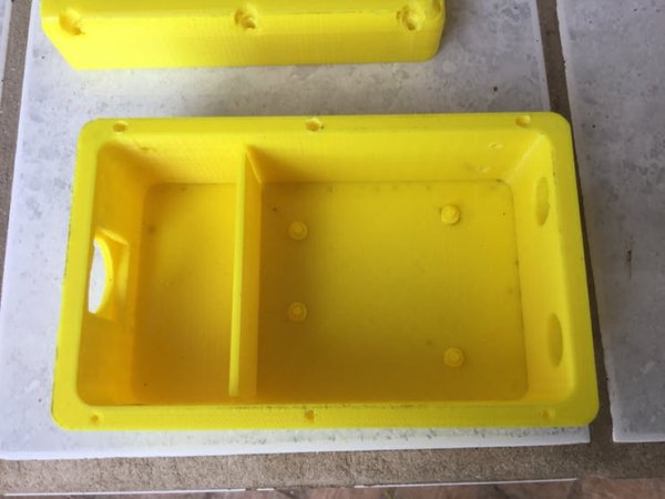
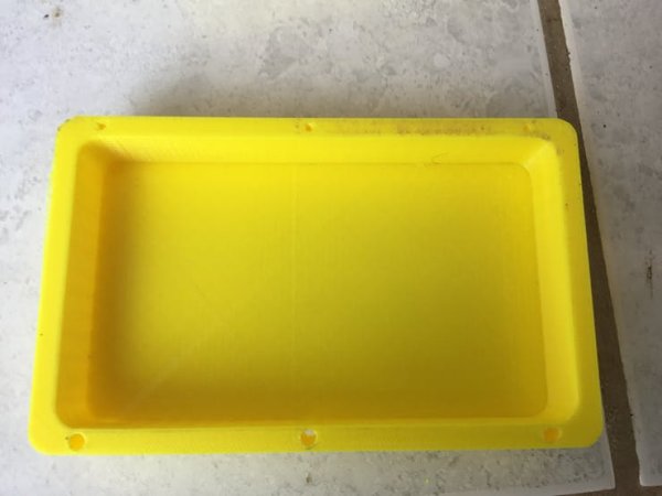
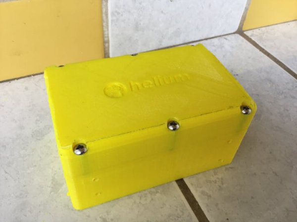
Putting Your Box Together (with Pictures)
The box will come in out as 7 different parts: main base box, left and right front legs, left and right back legs, lid and solar panel mount, and small solar clips. Build the box completely before putting it all together.
First clean up the 3D print.
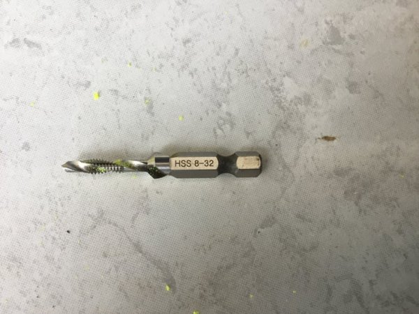
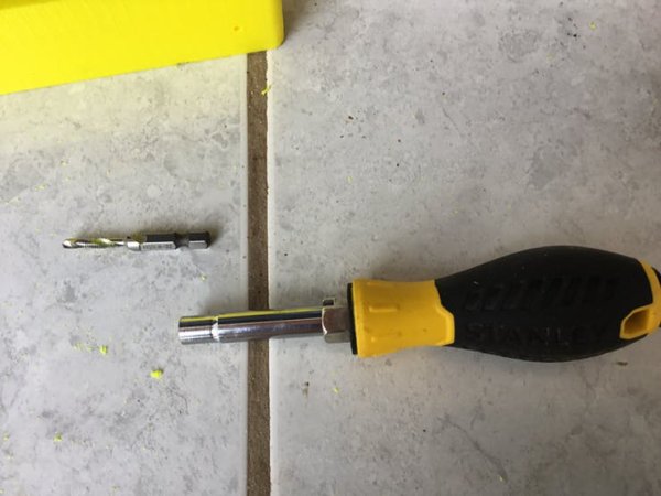
Step 1: Tap all holes with the 8-32 tap tool (by hand) since a drill is too fast. Secure the lid with 8-32 x 1″ x 6 (see pictures).
Read More Detail : Helium Air Quality Sensor