- Raspberry Pi
- 8GB SDHC Class 10 Card
- Nano Wifi-Stick
- Flytron Navigatron I2C GPS
- 4channel I2Csafe Bidirectional Logic Level Converter
- ADS1015 ADC
- Suppo A2212/13 1000KV Brushless Motor
- 10″x4.5 GF Propeller Set Orange 4 Stück 2 CW 2 CCW
- Flyduino HEXFET 20A Motor Controller
- Drotek IMU 10DOF: MPU9150 + MS5611
- MaxSonar I2XCL Ultrasonic Sensor
- I2C to PWM Converter
- DSL 4Top RC Receiver
- Graupner MX16 Transmitter
- Quadrotor center plate with on board power distribution
- 215mm Rigger Mikrokopter
- 3 or 4 cell lithium-polymer battery
In addition, you should have enough mounting materials such as cable ties, flat cable, soldering equipment, screws etc. on hand.
Preparations
First, the GPS receiver must be re-flashed. This is necessary due to an incompatibility with the standard I2C protocol. As the GPS receiver is based on Arduino, it can be flashed using the Arduino IDE. The required Arduino sketch can be downloaded here A guide to flash using a Arduino can be found here, section “Uploading Using an Arduino Board”.
The System image copter_20140624_zero.img.7z must be unpacked and copied to an SD card. It contains the Raspbian OS (Kernel 3.10) with the PenguPilot software. On Windows, the image can be copied using the tool Win32DiskImager. Under Linux, the command
dd if=/path/to/copter_20140624_zero.img of=/dev/<sd-card>
is sufficient. The SD card must have a capacity of 8GB at least!
Building the Quad
In the first step on the lower center of the plate battery connector with properly sized cables (2qmm) must be soldered. Subsequently, the aluminum profiles are bolted firmly with both centerplates.
Next, the motors have to be soldered to the motor controllers. It should be noted that the rotational direction of the motors depends on the connection of the three cables. To produce a moment of equilibrium, two motors must rotate in the opposite direction. Therefore, only two of the three wires need to be crossed. The motors that rotate in the same direction must be mounted opposite to the aluminum profiles. The motor controller will be soldered to the bottom center plate. To secure the motor controller, cable ties are used.
Figure 3
The correct direction of rotation of the motors can be seen in Figure 3. Furthermore, make sure that the red aluminum profile is in the front – Engine 1 In the chapter Commissioning is a guide to the direction of rotation to consider.
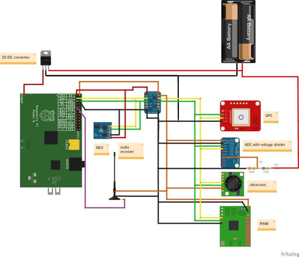
Next, the sensors need to be connected with the Raspberry Pi according to the circuit diagram as shown in Figure 4.
For more detail: List of required material


