Security is a major concern in our day to day life, and digital locks have become an important part of these security systems. There are many types technologies available to secure our place, like PIR Based security systems, RFID based Security system, Laser security alarms, bio-matrix systems etc.
We have previously built Digital Lock with Password using Arduino and using 8051, here we are going to build this Digital Lock using Raspberry Pi with User Defined Password. Once the password is set, user can only access the door with correct password.
If you are not familiar with Raspberry Pi, we have created a series of tutorials to learn Raspberry Pi, with interfacing with all the basic components and some simple projects to start with, do check.

Components Used:
- Raspberry Pi (with booted SD card)
- Keypad Module
- Buzzer
- 16×2 LCD
- 10k pot
- 10k Resistor Pack (Pull-up)
- LED
- 1k Resistor
- Bread board
- CD/DVD trolley as Gate
- Power 5 volt
- Motor driver L293D
- 12 Volt Battery
- Connecting wires
Connecting 4×4 Keypad with Raspberry Pi using Multiplexing:
In this circuit, we have used Multiplexing Technique to interface the keypad for entering the password in the system. Here we are using 4×4 multiplex keypad with 16 keys. Normally if we want to use 16 keys then we need 16 pins for connection to Arduino but in multiplexing technique we need only 8 pins for interfacing 16 keys. So that it is a smart way to interface a keypad module. Learn more about Multiplexing technique and its working in this Digital Lock using 8051.
Multiplexing technique is a very efficient way to reduce the number of pins used with microcontroller for providing input or password or numbers. Basically this technique is used in two ways – one is row scanning and other one is column scanning. If we use keypad library (#include <Keypad.h>), like we did in this Digital Code Lock using Arduino, then we do not need to write any multiplexing code for this system. We only need to use keypad library for providing input.
But here in this project, we have implemented a short way of coding for the same keypad, without using the keypad library. Please see it in programming section below.
Circuit Description:
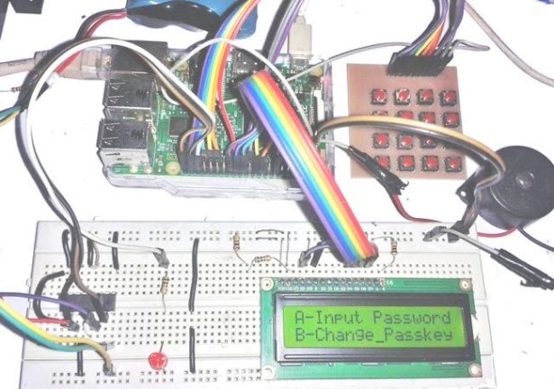
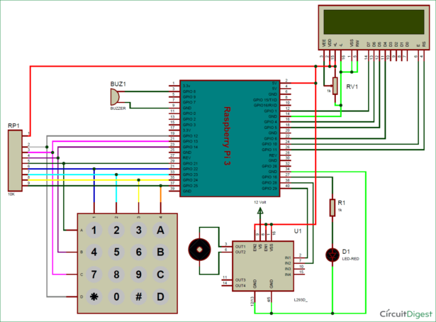
Circuit of this Raspberry Pi Digital Door Lock is very simple which contains Raspberry Pi 3, keypad module, buzzer, DVD/CD trolley as gate and LCD. Here Raspberry Pi controls the complete process like taking password form keypad module, comparing passwords, driving buzzer, opening/closing the gate and sending status to LCD display. Keypad is used for entering password. Buzzer is used for indications and driven by inbuilt NPN transistor. LCD is used for displaying status or messages on it.
For more detail: Raspberry Pi Digital Code Lock on Breadboard


