
The DS18B20 temperature sensor is well-suited for various projects such as weather stations and home automation systems. Its ease of setup on the Raspberry Pi makes it particularly convenient. The sensor is compact, similar in size to a transistor, and requires only a single wire for the data signal. Additionally, the DS18B20 sensor offers exceptional accuracy and performs measurements rapidly. To complete the setup, you will only need an additional component: a 4.7K Ohm or 10K Ohm resistor.

In this tutorial, I will guide you through the process of connecting the DS18B20 digital temperature sensor to your Raspberry Pi. Furthermore, I will demonstrate how to display the temperature readings on either the SSH terminal or a 16×2 LCD display.
The components used in this tutorial are as follows:
– DS18B20 Digital Temperature Sensor
– Raspberry Pi 3 B+
– 16×2 LCD Display
DIGITAL TEMPERATURE SENSORS VS. ANALOG TEMPERATURE SENSORS
Digital temperature sensors, such as the DS18B20, possess several distinct characteristics that set them apart from analog thermistors. In the case of thermistors, variations in temperature induce changes in the resistance of a ceramic or polymer semiconducting material. Typically, a thermistor is incorporated into a voltage divider circuit, where the voltage is measured between the thermistor and a known resistor. The measured voltage is then converted to resistance, and subsequently, the microcontroller converts this resistance value into a temperature reading.
On the other hand, digital temperature sensors are usually integrated circuits made of silicon. They encompass not only the temperature sensor itself but also an analog-to-digital converter (ADC), temporary memory for storing temperature readings, and an interface for communication with a microcontroller. Unlike analog temperature sensors, digital sensors perform internal calculations, and their output directly provides an actual temperature value without requiring further conversions by the microcontroller.
ABOUT THE DS18B20
The DS18B20 temperature sensor utilizes the “One-Wire” communication protocol, which is a proprietary serial communication protocol designed to transmit temperature readings using a single wire to the microcontroller.
One notable feature of the DS18B20 is its ability to operate in parasite power mode. Under normal circumstances, the DS18B20 requires three wires for operation: Vcc, ground, and data. However, in parasite mode, only the ground and data lines are utilized, and power is supplied through the data line itself.
Moreover, the DS18B20 includes an alarm function that can be configured to generate a signal when the temperature exceeds a high or low threshold set by the user.
The device incorporates a 64-bit ROM that stores a unique serial code, providing each DS18B20 sensor with a distinct address. This 64-bit address enables a microcontroller to receive temperature data from an extensive number of sensors connected to the same pin. The address assists the microcontroller in identifying which sensor corresponds to a specific temperature value.
TECHNICAL SPECIFICATIONS
The DS18B20 temperature sensor exhibits the following specifications and features:
– Temperature range: -55°C to 125°C
– Operating voltage: 3.0V to 5.0V
– Sampling time: 750 ms
– Resolution options: 0.5°C (9-bit), 0.25°C (10-bit), 0.125°C (11-bit), and 0.0625°C (12-bit)
– Unique 64-bit address for each sensor
– Utilizes the One-Wire communication protocol
These specifications highlight the temperature measurement range, operating voltage, sampling time, resolution options, and the unique addressing capability of the DS18B20 temperature sensor. The One-Wire communication protocol is used to facilitate communication between the sensor and the microcontroller.
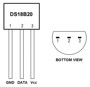
CONNECT THE DS18B20 TO THE RASPBERRY PI
The DS18B20 has three separate pins for ground, data, and Vcc:
WIRING FOR SSH TERMINAL OUTPUT
Follow this wiring diagram to output the temperature to an SSH terminal:
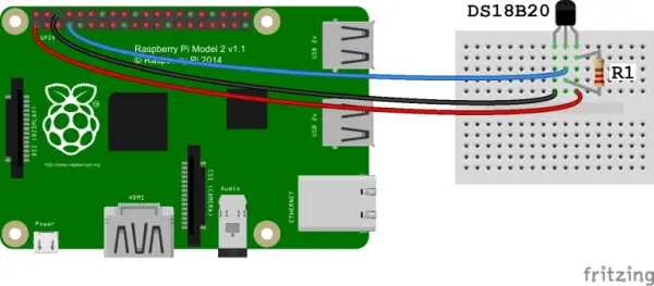
R1: 4.7K Ohm or 10K Ohm resistor
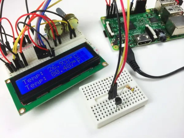
WIRING FOR LCD OUTPUT
Follow this diagram to output the temperature readings to an LCD:
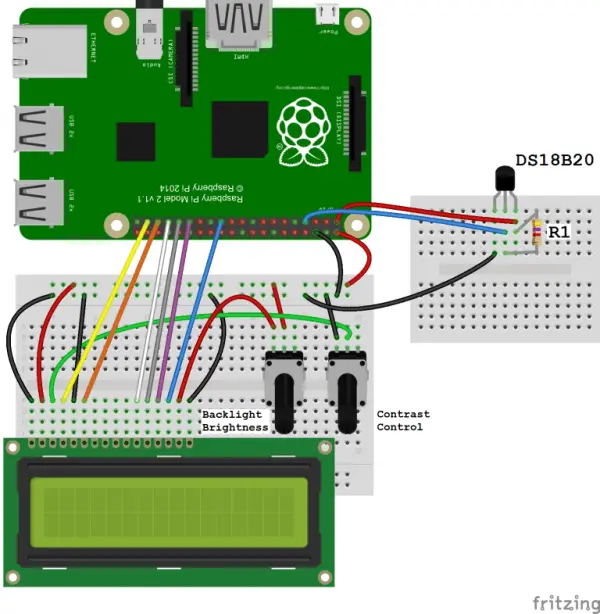
For the resistor in the circuit, you have the option to use either a 4.7K Ohm or a 10K Ohm resistor (referred to as R1).
If you are interested in learning more about utilizing an LCD display on the Raspberry Pi, I recommend checking out our tutorial titled “Raspberry Pi LCD Set Up and Programming in Python.” This tutorial provides detailed instructions on setting up and programming an LCD display specifically for the Raspberry Pi, offering additional information and guidance on this topic.
ENABLE THE ONE-WIRE INTERFACE
To ensure that the Raspberry Pi can receive data from the DS18B20 sensor, it's necessary to enable the One-Wire interface. Once you have connected the DS18B20 sensor and powered up your Raspberry Pi, follow these steps to enable the One-Wire interface:
1. Open the command prompt and enter the following command: `sudo nano /boot/config.txt`. This will open the config.txt file in the Nano text editor.
2. Scroll to the bottom of the file and add the following line: `dtoverlay=w1-gpio`.
3. Exit Nano by pressing Ctrl + X, then press Y to save the changes and Enter to confirm the file name.
4. Reboot the Raspberry Pi by entering the following command: `sudo reboot`.
5. Once the Raspberry Pi has restarted, log in again and open the command prompt.
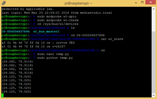
6. Enter the following command to load the required modules: `sudo modprobe w1-gpio`.

7. Enter the following command to load the w1-therm module: `sudo modprobe w1-therm`.
8. Change to the /sys/bus/w1/devices directory by entering: `cd /sys/bus/w1/devices`.
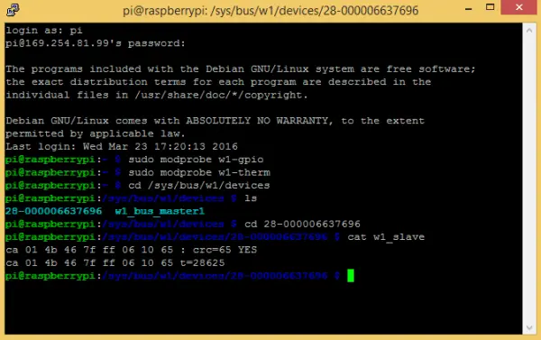
9. To verify the connected devices, enter: `ls`. This command will list the available devices.
By following these steps, you will successfully enable the One-Wire interface on your Raspberry Pi, allowing it to communicate with the DS18B20 temperature sensor.
PROGRAMMING THE TEMPERATURE SENSOR
The following examples are written in Python. If you are new to running Python programs, I recommend referring to our tutorial titled “How to Write and Run a Python Program on the Raspberry Pi.” This tutorial provides step-by-step instructions on saving and running Python files on the Raspberry Pi, offering guidance for beginners. It will help you understand the process of working with Python programs on the Raspberry Pi platform.
TEMPERATURE OUTPUT TO SSH TERMINAL
Below is a simple Python program that can be used to display temperature readings in both Fahrenheit and Celsius on your SSH terminal:
import os
import glob
import time
os.system(‘modprobe w1-gpio')
os.system(‘modprobe w1-therm')
base_dir = ‘/sys/bus/w1/devices/'
device_folder = glob.glob(base_dir + '28*')[0]
device_file = device_folder + ‘/w1_slave'
def read_temp_raw():
f = open(device_file, ‘r')
lines = f.readlines()
f.close()
return lines
def read_temp():
lines = read_temp_raw()
while lines[0].strip()[-3:] != ‘YES':
time.sleep(0.2)
lines = read_temp_raw()
equals_pos = lines[1].find(‘t=')
if equals_pos != -1:
temp_string = lines[1][equals_pos+2:]
temp_c = float(temp_string) / 1000.0
temp_f = temp_c * 9.0 / 5.0 + 32.0
return temp_c, temp_f
while True:
print(read_temp())
time.sleep(1)
TEMPERATURE OUTPUT TO AN LCD
To drive the LCD display, we will be utilizing a Python library called RPLCD. You can install the RPLCD library from the Python Package Index (PIP). If PIP is not already installed on your Raspberry Pi, you can install it by entering the following command in the command prompt:
import os
import glob
import time
from RPLCD import CharLCD
lcd = CharLCD(cols=16, rows=2, pin_rs=37, pin_e=35, pins_data=[33, 31, 29, 23])
os.system(‘modprobe w1-gpio')
os.system(‘modprobe w1-therm')
base_dir = ‘/sys/bus/w1/devices/'
device_folder = glob.glob(base_dir + '28*')[0]
device_file = device_folder + ‘/w1_slave'
def read_temp_raw():
f = open(device_file, ‘r')
lines = f.readlines()
f.close()
return lines
#CELSIUS CALCULATION
def read_temp_c():
lines = read_temp_raw()
while lines[0].strip()[-3:] != ‘YES':
time.sleep(0.2)
lines = read_temp_raw()
equals_pos = lines[1].find(‘t=')
if equals_pos != -1:
temp_string = lines[1][equals_pos+2:]
temp_c = int(temp_string) / 1000.0 # TEMP_STRING IS THE SENSOR OUTPUT, MAKE SURE IT'S AN INTEGER TO DO THE MATH
temp_c = str(round(temp_c, 1)) # ROUND THE RESULT TO 1 PLACE AFTER THE DECIMAL, THEN CONVERT IT TO A STRING
return temp_c
#FAHRENHEIT CALCULATION
def read_temp_f():
lines = read_temp_raw()
while lines[0].strip()[-3:] != ‘YES':
time.sleep(0.2)
lines = read_temp_raw()
equals_pos = lines[1].find(‘t=')
if equals_pos != -1:
temp_string = lines[1][equals_pos+2:]
temp_f = (int(temp_string) / 1000.0) * 9.0 / 5.0 + 32.0 # TEMP_STRING IS THE SENSOR OUTPUT, MAKE SURE IT'S AN INTEGER TO DO THE MATH
temp_f = str(round(temp_f, 1)) # ROUND THE RESULT TO 1 PLACE AFTER THE DECIMAL, THEN CONVERT IT TO A STRING
return temp_f
while True:
lcd.cursor_pos = (0, 0)
lcd.write_string(“Temp: ” + read_temp_c() + unichr(223) + “C”)
lcd.cursor_pos = (1, 0)
lcd.write_string(“Temp: ” + read_temp_f() + unichr(223) + “F”)
And with that, we have covered all the necessary steps! I hope you found this tutorial helpful and informative. If you would like to receive email notifications whenever we publish new tutorials, don't forget to subscribe. Feel free to share this tutorial with others who might find it useful. If you encounter any difficulties during the setup process or have any questions, please let us know in the comments section. We're here to assist you!