
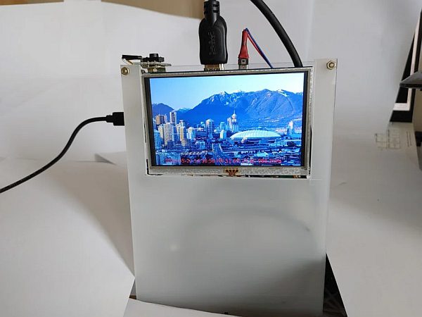
This is 5 inches LCD digital photo album using Raspberry Pi (RPI) Wireless Zero and a weather station device displaying humidity, temperature, and air pressure information.
Maybe this is the most upgraded and functionally versatile device among the weather station circuits I made before.
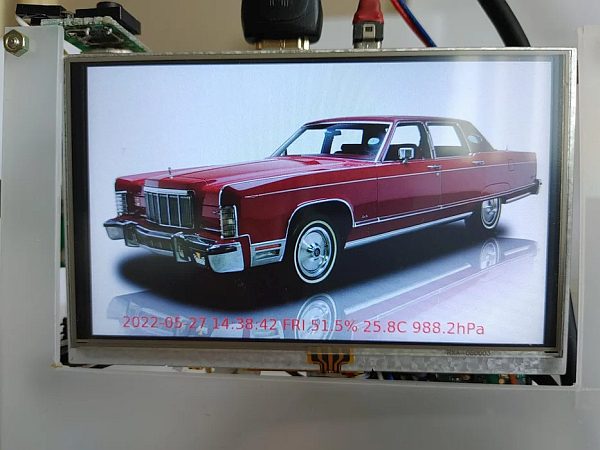
It can display high-quality photograph images on a wide LCD screen (5 inches).
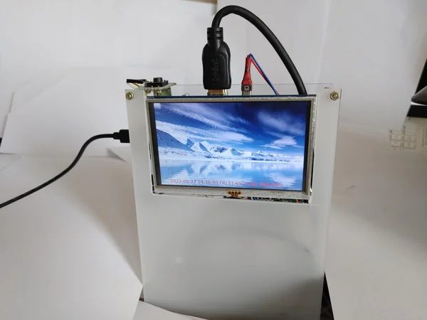
Also, it can show important weather information, and date/time on the LCD screen while enjoying the high-quality photo images.
Logging major weather data is possible along with timestamps for knowing long-term yearly climate change trends.
Let's see more detail about the RPI digital album and weather station circuit.
Step 1: Weather Station Circuit Upgrading History
About five different types of weather station circuits were made until now using 16×2 Dot-matrix LCD, 1.8 inch TFT, and 3.5 and 5 inches LCD.
As the display module size become bigger, the digital photo album function is integrated together for showing more versatile and enjoyable images.
You can see the previous weather circuits in the photo images above.
The first circuit is made with Arduino pro-mini and 1.8 inch TFT display.
As the DS3231 RTC and SD card break-out modules are used, it showed a one-year weather change trend across four seasons in Korea.
The disadvantage of this device is like below.
– As the internal flash memory of Arduino pro-mini is just 32KB, storing programs of the weather station and image album was quite difficult
– The 1.8-inch size display was so small for showing high-quality photo images on the LCD
The second circuit is made by using Arduino Mega2560 and 3.5 inch LCD module.
It operating for about six months and usually, I checked the time in the morning before leaving home to catch the bus going office.
But this circuit also has the following disadvantages.
– As the Chinese 3.5 inch, LCD manufacturer does not provide a compatible device driver, interfacing the display with Mega2560 was very difficult
– Also, the LCD manufacturer only supports a primitive image handling library, BMP file image was distorted when the resolution is not exactly 480×640 dpi
But the new device using RPI Zero and a 5-inch LCD module can remedy all previous problems due to the following reasons.
– As 32GB SD card is used for installing RPI OS, storing python program and image data, storage capacity is quite enough to support image photo album and storing many weather log files
– Because RPI and 5 inch LCD are connected with HDMI interface, I can utilize standard python graphic library and Tkinter X-windows application program
– RPI using time clock synchronization via NTP (Network Time Protocol), no additional RTC module (DS3231) is not necessary (But the RPI should be connected with wireless AP for receiving NTP time synchronization data)
Usually, the RPI development environment is more powerful than Arduino IDE, as RPI OS (Linux) can support various application development tools such as python, X-window, GPIO/I2C device interface related packages, and libraries.
Step 2: Schematics
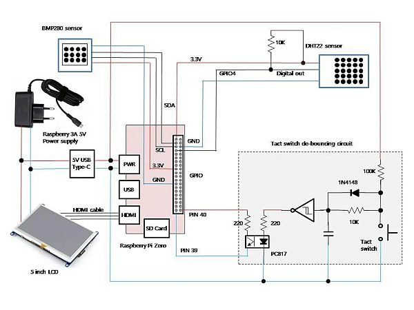
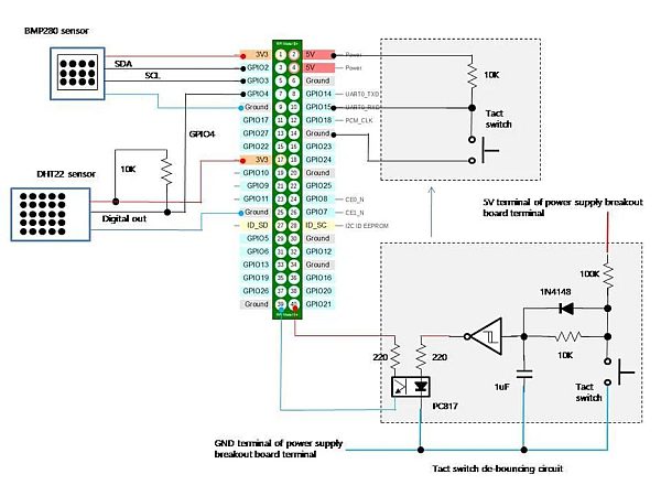
Although RPI is used, overall schematics is almost similar to the Arduino weather station circuit.
As mentioned above, the DS3231 RTC module is not necessary as RPI uses NTP for time data synchronization.
But you need a wireless connection to your home AP (Access Point) which connects to the internet and receives clock synchronization data from a level 0 clock source within the internet.
Because I'm interested in humidity, temperature, and air pressure of weather data, the DHT22 and BMP280 sensors are connected to RPI.
As both sensors are operating at 3.3 volts, two RPI Zero 3.3V power supply pins are used for connecting these sensors.
The 5-inch LCD module requires a 5V power supply for operation and an HDMI interface is needed for connection with RPI.
The tact switch de-bouncing circuit requires some explanation.
But you don't need such a complex circuit for your own project.
The followings are the reasons why I'm using such a complex circuit for simple tact switch input capturing.
– I want full proof of no-chattering making push-button circuit using 74HC14 (Schmitt−Trigger Inverter) IC
– As the RPI GPIO pin operating at a 3.3V level, I want completely isolate the de-bouncing circuit (Operating at 5V) from RPI by using an optocoupler (PC817)
The de-bouncing circuit only produces a single shoot of a pulse by the operational characteristic of the Schmitt−Trigger Inverter gate.
The tact switch is used to shut down the RPI or delete the image file displayed on the LCD. (I'll explain in detail at a later step when I'm explaining the python program)
Step 3: Parts
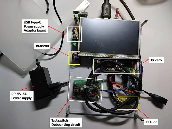
As the HDMI cable should be connected between the 5-inch LCD and RPI, the bulky cable needs to be housed inside the enclosure.
This cable hides several key parts of the digital album and weather station circuit in the photo above.
Anyway, the followings are major parts of making this circuit.
– Raspberry Pi Wireless Zero (with heatsink)
– 5 inch LCD (from Chinese manufacturer) supporting HDMI port and 5V USB type-B port, 800×480 resolution, HDMI cable
– DHT22 humidity and temperature sensor (3.3~5V support)
– BMP280 air pressure sensor (I2C interface and 3.3~5V support)
– Tact switch debouncer circuit part (Maybe you don't necessary these when you want to make circuit simpler): 74HC14 TTL IC, 1uF cap, 10K/100K resistors, IN4148 diode, tact switch, PC817 optocoupler, 220ohm resistors
– USB type-C power supply adaptor break-out board (Connecting external RPI 5V 3A power supply and RPI/5 inch LCD)
– 5V 3A power supply for RPI 3B
– Pinheader, PCB supporter, cables, universal PCB, USB type-B sockets
– Acrylic boards
As a 7×24 operation is required, the heatsink should be mounted on the RPI zero CPU.
Let's look at more detail of the circuit and how these parts are interconnected, configured, and assembled from the step below.
Step 4: Wiring and Assembling
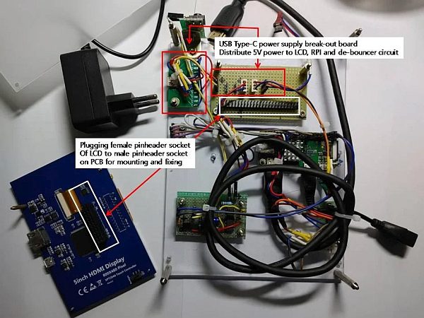
The first difficulty is how to mount and firmly fix a bulky 5-inch LCD on an acrylic board.
Finally, I figured out the LCD mounting method by using a male pin header socket (actually it's a 2×50 pin header block).
As a female pin header block is included in the 5-inch LCD module, these pin header sockets can be used for mounting and fixing LCD on acrylic board.
As HDMI cable is used for interfacing LCD to RPI, I don't need to use female pin headers of LCD module. (Therefore, no electrical connection should be made between pin header sockets)
Secondly 5V power should be supplied to RPI, LCD, and tact switch de-bouncing circuit (Using 74HC14 TTL IC).
I had bought 5V 3A power supply when using RPI 3B and 3B+ before.
This wall outlet power supply adaptor is connected to USB type C power supply break-out board.
The power supply break-out supports USB type-C input port and 5V and GND terminals to connect RPI, LCD, and other circuit for supplying power.
I'll explain in detail the connection method of the sensor with RPI in the step below.
Step 5: Sensors (DHT22, BMP280) Connection and Configuration
I had connected DHT22 and BMP280 sensors several times to Arduino until now.
Therefore, I'm very familiar with these sensors when I'm using Arduino.
But connecting those sensors to RPI is the first time with this project.
As hardware wiring is much straight forward and simple, I'll not explain in detail about that.
But software installation and configuration are a little bit different.
However, the overall method is very similar between Arduino IDE and RPI python library installation.
You need to install DHT22 and BMP280 python libraries with the following commands.
***
(DHT22 library install)
$ sudo pip3 install adafruit-circuitpython-dht
$ sudo apt-get install libgpiod2
(BMP280 library install)
$ sudo pip install bmp280
***
Although diverse other methods are explained on web pages, using the python module installer (pip3) seems the best method for avoiding python compiler errors (can't import module Adafruit_DHT or BMP280 modules) during programming.
I'm assuming you use “python version 3” for making the digital album and weather station program.
For the tact de-bouncing circuit, you can replace this circuit portion with a simple 10K resistor and tact switch wiring method which is well explained on many web pages.
Although every time the 74HC14 (Schmitt−Trigger Inverter) circuit produces just a single pulse of clean switch pressing input signal, it increases circuit complexity unnecessarily higher.
Why I'm using this circuit is that I had experienced several times with switch chattering problems while programming with python.
But as a result conventional 10K resistor and tact switch wiring method can support the required functionality very well.
Therefore, I'll not explain in detail about this circuit part.
Step 6: RPI X-windows Environment Configuration and Programming Preparation
Before looking at the python program, I'll explain several things about RPI OS configuration and installation of required python libraries.
The RPI OS usually turns off the X-windows screen when no input is available for several minutes (5~10 minutes).
For turning the X-windows screen (Therefore 5-inch LCD display) all the time, the following configuration is necessary.
Edit “/etc/xdg/lxsession/LXDE-pi/autostart” file for adding the following configuration parameters.
***
@xset s off
@xset -dpms
@xset s noblank
***
When the above parameters are configured, the X-windows screen never becomes blank (therefore not turning off the screen).
When RPI Zero is turned on, the digital album and weather station python program should be started automatically.
Therefore, the following configuration should be applied to “.bashrc” file in /home/pi.
***
(Insert the commend at the last line of .bashrc) sh +x /home/pi/view.sh
(view.sh contents is like below)
DISPLAY=:0.0 python3 /home/pi/viewer/00_Viewer_20220522_v6.py > /home/pi/log/view.log 2>&1
***
The side-effect of using “.bashrc” is that you can't access to shell prompt as the python program is automatically running.
Therefore, you should add an additional user such as “test” by using the “adduser” command.
Also, you need to change the root password for shutdown RPI when you connect the RPI using a remote terminal application such as Putty.
When you install RPI OS with X-windows desktop (default installation option), the “Tkinter” X-windows library is installed as default.
Therefore, you don't necessary to install any X-windows-related libraries.
But as I display JPEG images on canvas, the following additional library should be installed
***
sudo apt-get install python3-pil.imagetk
***
When the RPI OS configuration is finished like above, we are ready to make a python program which will be explained in the step next.
Step 7: Tkinter Based Python Program
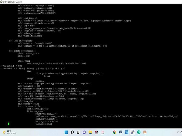
The most difficult part of this project is not hardware wiring and configuration.
Rather making an X-windows-based python program is the hardest part for me.
As I get used to making procedural python programs, the MVC (Model-View-Controller) based X-windows programming is a kind of challenge.
Still, I'm struggling to get used to the MVC-based programming style.
Therefore, I searched for a sample X-windows program code that shows JPEG images on the Internet.
Afterward, I modified the sample program to suit my requirements for making the digital album and weather station application.
The first difficulty I faced is MVC needs external events (such as mouse click or entering keyboard and so on) for activating certain parts of the program.
But my application needs to run by itself (Showing images and displaying weather data continually) without any intervention.
Therefore the following code is included in the application code.
***
self.window.after(3000, self.update_screen)
***
Per every 3 seconds, main window updating (call windows-updating code itself) is performed for showing images and displaying weather data continually.
I don't think my code is a good example as I only focused on the code just running anyway without applying any program optimizations.
You can see the program code in the file attached to this step.
Actually, a single object (ImageViwer) encapsulates all required functionalities like below.
***
– Initiating 800×480 size of the main window for displaying JPEG files
– load JPEG image from the /home/pi/IMAGE directory randomly
– loaded image is manipulated to fit the 800×480 window (Canvas) and checks whether the tact switch is pushed
– When the tact switch is pushed program automatically shutdown RPI
– Although the JPEG file deleting function is included, it is not used as the switch is utilized for shutdown RPI
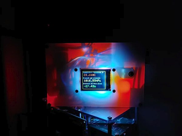
– Along with the JPEG image, date/time and weather data (humidity, temperature, air pressure) are displayed and stored in the log file
***
Originally the tact switch is added to delete the unwanted image that is displayed on the LCD.
But I changed the function of switch to shutdown RPI if turn off is necessary (But usually power off will not be necessary as it should be operated as a 7×24 scheme)
Please look at the code in the file below for more detail about the python program.
Step 8: Digital Album and Weather Station Operation
As the conclusion of this RPI project, you can see the digital album and weather station operation captured as video in the link below.
***
https://drive.google.com/file/d/1pxHMS2PxvFEQ2BUBbkmd0aJALopA-MZB/view?usp=sharing
***
Sometimes red-colored date/time/weather data string can't be seen if the bottom side of the JPEG image background color is reddish.
But soon or later, you can see the text message when other JPEG images are displayed on LCD.
***
Thank you for reading this project story…..
Source: RPI and 5 Inch LCD Digital Album and Weather Station