
Have you ever had one of those moments, when you’re rummaging through your spare parts heap, and have a rather bizarre project idea that you can’t quite get out of your head? You know, the ones that have no clear use, but simply demand to be born, of glass and steel and silicon?
Have you ever had one of those moments, when you’re rummaging through your spare parts heap, and have a rather bizarre project idea that you can’t quite get out of your head? You know, the ones that have no clear use, but simply demand to be born, of glass and steel and silicon?
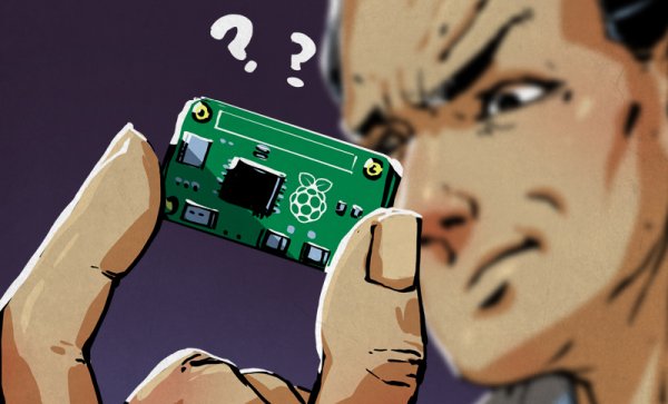
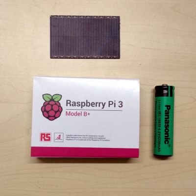
This time, the stubborn idea in question was sort of like a solar-rechargeable LED throwie, but instead of a blinking light, it has a fully cloud-accessible embedded Linux server in the form of a Raspberry Pi 3 Model B+. Your choice of embedded Linux board should work — I just happen to have a lot of these due to a shipping error.
There were two main challenges here: First, it would have to combine the smallest practical combination of solar panel, power supply, and Li-ion cell that could run the Raspberry Pi. Second, we’ll need to remotely activate and access the Pi regardless of where it is, as well as be able to connect it to WiFi without direct physical access. In this article we’ll be dealing with the first set of problems — stay tuned for the rest.
SIPPING ON SOLAR
I approached the first challenge from the standpoint that the Raspberry Pi doesn’t need to be on all that often. An ESP8266 (Wemos D1 Mini) running NodeMCU can provide battery management, and receive commands over MQTT to activate it, while staying in deep sleep mode most of the time. This consumes very little power, allowing a small 5 volt solar module to trickle-charge a lithium ion cell large enough to power the server for a few hours of run time.
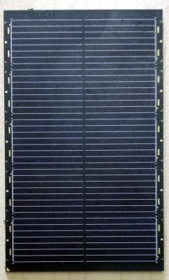
The solar modules are worth a quick mention. They are the LR0GC02(PDF) from Sharp, designed to trickle charge a variety of mobile electronics. Unlike a lot of modules out there, they are both extremely well encapsulated and very thin (about 1mm). They also come with detailed specifications. A single 300mW module is enough for this project, but I used three in parallel during development to speed up various tests. This tiny solar power module would also have been an interesting choice.
Managing the power from these modules is where things get a little hairy. We have a 4-5V power source charging a Li-ion cell that has a nominal output voltage of 3.7V. Then we have an ESP8266 module, which runs at 3.3V but can accept higher through an integrated linear regulator, as long as you watch the dropout voltage. Finally, we need a 5V output that can be easily toggled to power the Raspberry Pi. Also it would be nice to have a 12V line for future expansion.
MAGNIFICENCE OF MODERN MODULES
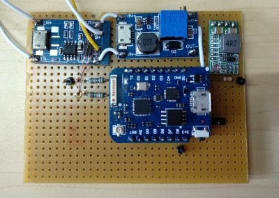
Thankfully that all sounds worse than it actually is, and there are some very common modules that will sort this out for us:
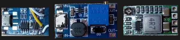
From left to right: A USB lithium ion cell charger, a DC-DC boost converter, and a DC-DC buck converter. They cost about a US dollar each, which was great value!
The first stage is a USB lithium ion cell charging module. These accept the ~5 V output from our solar panels, and will safely charge our cell. The output of the module is whatever the Li-ion cell voltage is.
Next in line, I added a DC-DC boost converter module set to output 12V. These modules are better than 90% efficient, accept a range of voltages, and will output a fixed voltage that is set by a trimpot. The 12V output is connected to the linear regulator on the ESP8266. This way, even if the cell voltage drops below around 3.7V, it will continue to function. This is critical as the ESP8266 monitors the Li-ion cell and switches the server on and off. If we were to connect its linear regulator directly to the cell output, it would shut down due to power loss while there was still quite a bit of usable power in the system. We do lose a bit of efficiency here, but the ESP8266 is off most of the time, so I can tolerate that.
The 12V output is then fed into a DC-DC buck converter to drop the voltage down to 5V for the Raspberry Pi. It’s important to use a buck converter with an enable pin, so we can control the output state using the ESP8266 later on. Otherwise you’ll need to add a MOSFET or similar to control the power output.
RESPONSIBLE BATTERY MANAGEMENT
At this point, we have all the voltage levels we need, and charge control circuitry to prevent our Li-ion cell from engaging in spontaneous unplanned combustion. However, when lithium ion cells are discharged too far, they cannot be safely charged again. We need to monitor the cell and prevent it from rendering itself into an unusual paperweight.
The solution is quite straightforward: the ESP8266 has an analog to digital converter. It can only accept up to 3.3V, and our cell can supply more than this, so I used a couple of 100kΩ resistors set up as a voltage divider to drop the voltage – we don’t exactly need high precision here.
To start our control program, I set a timer to run the ESP8266 for 11 seconds before sleeping for 10 minutes, this is plenty of time for the chip to check for commands online. Then, if the cell voltage is below 3.4 volts, it will immediately sleep for 16 minutes instead.
function checkvolt()
x = adc.read(0)
print (x)
if x < 528 then
print(“low battery, sleeping longer”)
node.dsleep(960000000)
end
end
checkvolt()
function sleeping()
node.dsleep(600000000)
end
tmr.alarm(0,11000,0,sleeping)
Some rough calculations suggest that the module will consume an average of around 1.5 mA normally, and around 0.2mA if the cell voltage is low. In reality there will be some current consumed by all the parts even while the system sleeps. I’m told that the sun shines at least once every month or so (I’ll check at some point), and the cell should not have trouble maintaining charge. In any case, if the former assumption is wrong, I have bigger problems to deal with.
REGULATING THE VOLTAGE REGULATOR
Finally, we need to be able to control the output of 5V from the last voltage regulator. While I purchased a module that had an ‘enable’ pin available, there was no documentation as to how it worked, and the exact chip used in my module was unclear. Looking at datasheets for a few ICs from different DC-DC converters, it looked like it was probably an active-high enable pin that was pulled up with a resistor on the module.
I tried pulling it back down with a 50kΩ resistor, and the voltage output dropped to zero. Supplying 3.3 volts from one of the GPIO pins of the ESP8266 triggered the enable pin, and it output 5V again.
I discharged the cell a little, then left it running in the sun for an hour – it recharged a bit as expected, prompting the requisite maniacal laughter. Power stages… complete!
WHERE’S THE LINUX?
It’s small, it’s solar powered, but other than lounging about in the sun, it doesn’t really do anything yet. Most computing hardware requires software and obviously this is no exception — so how do we make this into a lean, green, Linux machine?
In the next article, we’ll cover how to control this system via MQTT, set up remote configuration (for example if I need to change my WiFi password), and set up a reverse-SSH tunnel so we can connect to the Raspberry Pi without having to reconfigure our network to accommodate it.
The irony that my servers now get more sun than I do is not lost on me. I live near the equator though, and sunbathing for extended periods is an activity reserved for tourists – one that they normally learn to avoid pretty quickly!