
Over the last year and a half I have bought four Raspberry Pis. Each Pi has been the centre piece of four different projects.
The first Pi navigates the FishPi Proof-Of-Concept Vehicle, the second manages the FishPi POCV Base-Staion, the third has been tightly packed into the worlds first Raspberry Pi Netbook, and the fourth now powers the LittleBox prototypes.
So what is a LittleBox?
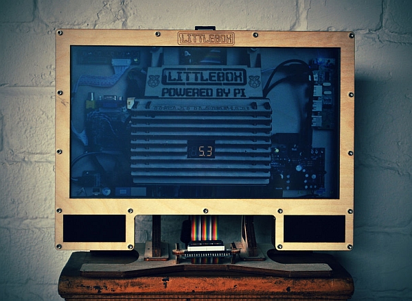
- Raspberry Pi Powered All-In-One Desktop PC.
- 14″ Widescreen LED Back-light LCD.
- Resistive Touch Screen.
- Integrated Amplifier & Speakers.
- Integrated USB Hub.
- Built-In Power Converter.
- GPIO Header.
- Laser Cut Birch Plywood Frame & Stand.
- Build-It-Yourself Kit.
- Runs from a 12v PSU.
This instructable follows my development of the LittleBox from a thought bubble, to a prototype, and finally to a KickStarter project.
The LittleBox is on Kickstarter | http://www.kickstarter.com/projects/1008225922/littlebox-the-diy-raspberry-pi-all-in-one-desktop
Although the LittleBox didn't reach its funding target on Kickstarter the LittleBox is still available as a bare-bones kit. Details are at http://thelittlebox.co/theshop
The LittleBox came runner-up in the Epilog Challenge V! Thanks to everyone who voted | http://www.instructables.com/contest/epilogv/
Step 1: The Thought Bubble
Crossing the Atlantic is a complicated challenge, and one that I have decided to accept. The FishPi Project hopes to use a Raspberry Pi to navigate a drone across the Atlantic Ocean.
The first step in this quest has been the building of a Proof-Of-Concept-Vehicle (POCV), and a controlling terminal called the Base-Station.
The Base-Station is an aluminium flight case fitted with a Raspberry Pi, a screen, keyboard & trackball, a USB hub, and a wireless router. It will be used to manage the POCV, handle the telemetry, and monitor the POCV's performance.
I'd like everyone to be able to follow the POCV during testing, watch as the FishPi makes it's way across the Atlantic Ocean, and monitor our progress along the way. What if everyone had their own Base-Station to do this?
To build the FishPi Base-Station has taken over a year. It's also designed for a specific purpose; that of controlling the POCV. Any Base-Station for use by everyone else would not need to be quite so specific in its use.
Better yet, rather than a Base-Station, what about a Raspberry Pi Desktop PC?
Brilliant idea!
So what would I want from a Raspberry Pi Desktop PC?
- I'd want to be able to build it myself. The Raspberry Pi has sparked a maker revolution, it would be rude not to design a Build-It-Yourself kit.
- One thing I learnt from the Base-Staion, the POCV, & the LapPi Netbook is that you'll always need access to the components. I spent a lot of time taking the three apart just to wiggle a wire, or change a part, so the LittleBox electronics must be easily accessible.
- The SD Card must also be easy to reach. I'd like to be able to swap SD Cards around so I can have multiple Operating Systems and distributions easily available.
- Not too big, or not too small. Screen Size. Widescreen so I get the best cinematic experience if I want to watch films on the LittleBox, but I don't want it too heavy or cumbersome in case I want to take my LittleBox out to a HackSpace or a friends house.
- I'll need sound to go with the films. Decent speakers and an amplifier are essential.
- Powered USB, the Raspberry Pi suffers if too much current is drawn from it. I'll need a powered USB Hub, and I'll need a power source to drive it.
- Access to the GPIO Header. I don't want to have to poke around if I fancy plugging in the GPIO header to a breadboard. I'll need to bring the GPIO in from the cold and out in front of the LittleBox.
Now if I can get all of that into one design I might be onto a winner!
Step 2: The Basics & First Preparations
After some thinking I have decided that the LittleBox is to be built around a 14″ LED Back-light LCD. I've also chosen a matching touch screen. I've gone for a smaller screen so the LittleBox is lightweight and easy to handle.
The design is based on the All-In-One PC form-factor. I'll have amplified sound via the headphones socket on the Pi, a USB Hub, access to the GPIO, and an in built power supply to change from an input of 12v DC down to 5.2v for the USB hub and the Raspberry Pi. I'm hoping to find a USB hub which can back-power the Raspberry Pi as the Pi's Micro USB power port will be obstructed by the LittleBox case.
The LittleBox case is to be laser-cut from plywood and assembled in layers. A single layer will hold all the components and the frame will be bolted together.
I've assembled most of the major components already. Time to get on with things. I have picked the RKAmp2 2 x 2.5 watt amplifier from RK Education. I used the smaller 2 x 1 watt amplifier in the LapPi Netbook.
In the Beginning.
The RKAmp2 comes in a kit, so the first step is putting this kit together. There are no step-by-step instructions provided with the kit, but there is documentation on the RK Education Website.
When finished making the amplifier it's always a good idea to test it. Connect a set of wires to the speakers, try and solder them so that the negative & positive wires are the same on both speakers.
Once the amplifier has been tested as working now would be a good time to plug together the Raspberry Pi, LCD & control boards, and any ancillaries you plan to use with your design, such as USB Hubs, keyboards, mice etc.
During this checking stage I tested different configurations in the /boot/config.txt file on the Raspbian SD Card to find the best settings for the LCD.
Step 3: On With The Prototyping
I have had some trouble finding a USB Hub which would be suitable for the job. I was looking for a hub with a low profile, and one which could feed back +5v to the Raspberry Pi. The first Hub I tried had four ports, I thought I could use two; one for four internal ports, and another for four external ports. The Basic USB Block hub was exactly as it described, basic. I quickly ruled it out as too flimsy.
The next was the Belkin F5U701-BLK. It looked perfect for the job, but after checking the eLinux.org list of RPi Verified Peripherals it turns out that that particular Hub does not work well with the Raspberry Pi. I should have probably checked the list before buying one!
The third is a generic 7-Port hub. It is both low profile, and it feeds power back to the Raspberry Pi. The other point I needed to check was availability, and there are lots of them around so we are ok on that point too.
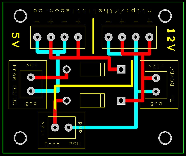
I've plumped for a 12v feed from a mains powered PSU to power the LittleBox. This will keep the high voltages away from anyone building, and using, a LittleBox. I'll be using a 12v DC DC converter which is capable of out-putting 5v @ 5A. That should be plenty.
I did some testing with the LCD and while the manufacturers datasheet for the LCD logic board states it will function at 5v, I found that the screen flickered at 5v, but not at 12v. So I decided on using a 12v input, directly powering the LCD and also directly supplying the DC DC converter with 12v too.
Using the DesignSpark PCB software I drew up a simple circuit. This circuit will help keep the wiring tidy, and safe. It essentially routes power from the PSU to the DC DC Converter, takes a feed back from the converter and then allows for up to three devices to run from a +5v supply. There is also a +12v feed for the LCD. Both circuits pass through rectifier diodes to protect against reverse polarity.
Step 4: Where to start
I'll be using laser cutting technology as the manufacturing method for the LittleBox, but before we can start we need to know what our design constraints are. After doing some research on the internet I found a company called Cut Laser Cut. They are based in London so they should be perfect for my needs.
They have a section explaining their design requirements, They also have a huge list of materials to choose from, and most importantly they have prepared templates so you can plan your design to work within your chosen material's sheet sizes.
I have decided to try and use a single 1500mm by 1200mm sheet of 3mm Birch plywood to make one LittleBox. The LittleBox is to be built up in 3mm layers. The first of these layers is the front fascia. From the Fascia I will create all the other layers building up the LittleBox in 3mm steps.
My first try at this I just copied the previous layer, but any minor differences and errors were exaggerated with each copy & paste of the last layer. The solution was to use a master copy, in this case the Fascia, and copy & paste from that. That meant that the Fascia had to be perfect, and it would need to have all the recurring features so they could be accurately transferred to the other layers. I must admit it took me a few goes to get it right.
I want to engrave the front Fascia with the LittleBox logo. Having the layers all pointing up means that I can raster engrave the plywood with instructions for when I come to build it. I can also number the layers too. When the LittleBox is assembled any laser engraving will be hidden apart from the logo on the Fascia.
There are several factors which need to be considered while drawing the Fascia. Firstly there is the difference between the LCD's outer dimensions, and it's viewable area. Because of this the Fascia will have a larger border than the following layers. Next we will need to consider the cable connector from the touch panel. We will need a cut-out so the cable can pass unhindered otherwise we risk damage to the touch panel. Lastly we will need somewhere for the speakers to go.
Now that we know what to plan for and what restrictions we are under we can get started with the LCD.
1 | To begin measure the dimensions of the viewable area of the LCD. The simplest of methods is to turn the LCD on and then measure with a ruler.
2 | Transfer the measurements into a digital medium. There are plenty around.
3 | Measure the LCD's outer dimensions.
4 | Next are the outer edges. I have given the LittleBox a 10mm border around the edge of the LCD. Remember that the viewable area is smaller than the actual outer dimensions of the LCD so it will appear to have a larger border around the LCD.
I found it helpful to have both measurements viewable at the same time, that way you are able to see if you are going outside the bounds of the border. On the next layer the edges will be more obvious as we will no longer be working with the viewable area.
5 | The Speakers measure 28mm square, To allow for a bit of inaccuracy in the manufacturing I went with a cut-out size of 28.5mm square. To keep things simple I decided to have them positioned below the screen. The Speakers have a 10mm border around them too.
6 | I have chosen M3 (3mm) screws to hold the LittleBox together. I marked 3.25mm bolt holes along the 10mm Border around the LCD & Speakers. The hole centres are 5mm from the outside edges.
7 | The cable for the touch screen extends past the outer dimension of the LCD. A cut-out has to be made into the outer border to allow the cable to pass through. We don't need a cut-out in the fascia but the next few layers will do.
I now have the master template, the Fascia, ready.
8 | Copy the Fascia and paste as a new layer. I have called mine layer One.
9 | Layer One needs to have the full LCD dimensions, so the border is 10mm wide. The cut-out for the touch cable is required on this layer too.
The combined thickness of the LCD with the Touch Panel is approximately 6mm. To give room for the cable which will plug into the LCD I will add an extra 3mm layer giving a total height of 9mm. My plan is to use strips of 3mm foam behind the LCD to keep it in place.
10 | Create a new layer, Two, and past from the Fascia Master copy.
11 | Layer Two will be modified to include screw holes for the speakers. I filled in the four corners of the speaker cut-outs and marked 0.6mm holes for M1 (1mm) self tapping screws. Make sure to take measurements from the speakers to ensure accurate mounting of the speakers.
12 | Create layer Three. Layer Three requires no modifications and is identical to layer One, apart from the numbering.
The Fascia and the three layers are enough to keep the Touch Panel & LCD firmly in position. Next we'll add a layer for the electronics to attach to, and continue to layer up the LittleBox.
Step 5: Layer Cake
The traditional method for a Nut & Bolt fixing, is a Nut & Bolt. However I am going to test a different method; Insert & Bolt.
Threaded Brass Inserts as they are known to those in the know, provide fixing points inside all manner of products. You're most likely to find them in plastics, in Laptops for example, which is where I know them from as I spent six years working as a Laptop engineer.
Tappex are a UK company which manufactures Threaded Brass Inserts. I will be using their line of Microbarb inserts as anchor points for the screws and bolts holding the LittleBox together. The Inserts are captive so if for any reason I need to take apart the LittleBox I shouldn't lose any fixings, which is what might have happened had I decided on using nuts.
Layer Four of the LittleBox will not have the centre cut out like all the other layers. I will cut holes to take a selection of inserts which will act as anchors for screws holding the electronics in the LittleBox. The Tappex website provides specifications for the diameter of the holes needed for each insert size. For example an M3 Microbarb brass insert requires a hole of 4.66mm. Having previously checked the cutting specifications (Kerf) with CLC I know to expect a loss of material of approximately 0.1mm. Taking those specifications for an M3 insert hole I drew a hole diameter of 4.6mm (whether this is too large a hole I will see when the relevant parts arrive).
1 | Create layer Four. Make sure to remove the cutting lines for the viewable area of the LCD and the LCD's outer dimensions. You should have a solid layer where we can mark cut-holes for the inserts. Leave the touch cable cut-out and of course the speaker cut-outs.
When marking cut-holes for mounting the PCBs remember that you are looking at the layer from the front and that the PCBs will be mounted from the back. Any cut-holes are mirrored looking at them from the front.
2 | Turn the LCD face down. Position the PCBs on the back of the LCD where you want them to go. I placed the Raspberry Pi so that the SD Card sticks out the middle of the LittleBox at the top.
3 | Mark cut-holes for each of the PCBs that are going into the LittleBox (remember to mirror the holes). Don't forget a cut-out for the LCD harness to pass through. Each hole has text next to it saying which Microbarb insert should be fitted.
I took measurements for the Raspberry Pi from a template, measurements for the Logic Board are included in the datasheet, and the rest I had to measure by hand. Remember when placing the PCBs that you'll need to leave at least a 10mm gap around the outer edges. Consider to, the connections to the PCBs like headphone jacks, power inputs, and USB plugs, they all need clearance from not only the sides but each other.
All the PCBs sit on 3mm spacers, with the exception of the M4 mounted PCB (RKAmp2) which rests on 4mm spacers.
4 | Copy & Paste the Fascia into layer Five.
5 | Create cut-lines at the top for the SD Card to go into the Raspberry Pi.
6 | Draw two cut-lines 5mm apart on the centre of the upper boarder for the two speakers. The speaker wires will pass through these holes.
The USB Hub has no mounting holes so we have to get creative. I'm going to alter the border so it can be used to hold the hub in place. I'll have to take into account the M3 screw which will have to be routed between the lower two USB sockets. I'll be using an 18mm M3 spacer so the plywood isn't bent when the screw is tightened.
On the base of the USB Hub's PCB I plan to stick some strips of 3mm foam. This wil help to hold the hub but also keep any through-hole wires off of layer Four.
7 | Measure the Hub.
8 | Draw two cut-lines making space for the hub.
9 | Copy & Paste the Fascia into layer Six.
10 | Duplicate the cut-lines for the Hub. Centre of the 10mm border around the base of the speakers draw two cut-lines 10mm apart. This will create a hole to help improve the speakers bass performance.
11 | Copy & Paste the Fascia into layer Seven, and duplicate the cut-lines for the USB hub.
12 | Copy & Paste the Fascia into layer Eight.
13 | Alter the border so that the plywood slots between the USB sockets.
14 | Create two cut-outs for M2 Microbarbs, to help strengthen the assembly.
The LittleBox has a stand, and the stand will enclose the DC DC Converter and the Power PCB designed in Step 3. The stand has to attach to the screen pack so we must add brackets to do so. We'll be using M6 Microbarbs as part of the brackets.
I put the brackets for the stand near where the M3 screws are to go. Doing so should help combat any stresses in the wood and increase the strength around the bracket area.
15 | Modify the cut-lines around the two top and bottom centre M3 holes so that you can fit in brackets to hold four M6 Microbarbs.
16 | Copy & Paste the Fascia into layer Nine.
17 | Duplicate the alterations for the USB Hub remembering to reduce the M2 hole sizes, but do not copy the brackets.
18 | Copy & Paste the Fascia into layer Ten.
19 | Duplicate the alterations for the USB Hub, and the brackets remembering to reduce the size of the M6 holes.
20 | Copy & Paste the Fascia into layer Eleven.
21 | This is the final layer so we wont need to make any alterations but you will need to remove the cut-lines for the speakers, and increase the size of the M3 holes to take Microbarbs. I also put in a note to say the brass inserts should be inserted from the other side.
Step 6: Standing Orders
When I began with the stand I had an idea of what I wanted to do already formed in my head. Several factors I had to consider were to make the connection between the stand and the foot-plate as low as possible. Why? Well the screen pack needs some forwards & backwards adjustment, to help with viewing angles etc, but I also want to have a breakout board for the Raspberry Pi's GPIO header accessible from in front of the screen. If the point of rotation is high up then when the screen turns the bottom edge of the screen pack could very well hit against the GPIO break-out. So if I put the hinge low down there will be the smallest amounts of travel when the screen pack is tilted back & forth.
In addition to the hinge I also needed to find a home for the DC DC Converter, the Power PCB, a switch, and two input sockets (DC & CAT5e). I wanted to have all of this hidden away as much as possible.
The last consideration was the change in plane of the layers, from the face down position of the screen pack to the upright and vertical stance of the stand.
To hold the stand to the screen I have sandwiched four layers of 3mm ply, two on the screen back. Which is why layer 9 didn't have the brackets added but layers 8 & 10 did. The brackets will be held with M6 metal bolts. Then several uprights are glued to the brackets. You'll have a better idea of what I have done by looking at the drawings and of course looking at the finished stand & foot plate assembly.
In the end I came up with a single board onto which I would attach the DC DC Converter & the Power Board. To make them fit I have them positioned either side of a single main board in the stand. I've then added slats behind and on top of the assembly to hide the electronics whilst still giving plenty of space for air movement around the components.
The foot plate features some 36 M1 self tapper screws which hold 3 layers of 3mm plywood together. There are two 9mm (3 x 3mm) brackets which the stand uses to connect to the foot plate. I've also put in spaces for four rubber feet.
To save wood I put all the parts for the stand and what I could of the foot plate inside the screen pack frames.
Throughout the three weeks it took me to come up with the design I have had to refer to countless datasheets, schematics, and Google to find the best suited components for the job. If I have done my job right everything should go together without a problem. LOL.
The next thing to do now that the design is all done, is to get it laser cut, a total of 54 parts!
Step 7: 3D
While I waited for the post to arrive I loaded up Autodesk 123D and began to model the LittleBox in 3D.
It's very simple to use, free, and you can get some very good results!
I have attached two zipped Autodesk .123dx files. They are of the LittleBox exploded view, and the LittleBox assembled. The models aren't 100% accurate, they are for display purposes only!
 LittleBox.zip1 MB
Step 8: Frickin' Laser Beams
There's 53 parts there, technically 54, but you'll have to be extra sneaky to spot the last one.
The guys at Cut Laser Cut priced up my design with all the raster engraving I had done and advised me that I could make quite a large drop in cost by using vector lines instead of full engraving. So I have swapped all the words, instructions, and numbers to RGB Blue vector lines, but I left the LittleBox logo as is!
I'm very pleased with the results. There are some alterations to do, especially around the LittleBox Powered By Pi plate. Some of the gaps need widening too. The final version will be cut on a different laser machine so there should, I am hoping, be considerably less burn marks. It was explained to me that for this run there might be quite a few. It's not a problem at this stage.
The raster engraved LittleBox logo is very clean cut, it looks very good.
Cut Laser Cut sent all the scraps from the inside of the layers with all the parts I wanted.
Step 9: Assembly | The Screen Pack
There is something to be said about the combined emotions of excitement & fear. The LittleBox is ready to be built, but it is untested and I have quite a lot of time and money invested. What if I have got it wrong!
The best way to alleviate my fears and to help manage my excitement, is to begin with the build. I start with the fascia face down, and begin slotting in screws. It took a bit of practice to get them all in. The problem is that as you lift the fascia up to pop in a bolt, one that you put in before drops out. Anyway with a few minutes practice I managed to get all 18 in.
To my relief the touch panel & the LCD fit perfectly. The cut-out for the touch cable is also in the right place.
Layer four needs some Microbarbs fitting. I used a hammer and knocked the inserts into the plywood, I placed a scrap bit of plywood between the hammer and the inserts to prevent any damage to the brass. The inserts have a flange which sits against the plywood so the inserts are not pulled through when they are tightened up.
I have some 12 x 3mm neoprene foam strip to stick to the front of layer four. The foam will press against the LCD holding the panel firmly in place. I only want the foam around the edges of the LCD in case it puts too much pressure on the LCD causing damage. I had to draw pencil lines onto layer four so I knew where to stick the foam. I have altered the vector lines so that the production run will have the guides vector engraved onto the layer.
When I first fit layer four it turned out that the 12mm x 3mm foam was too thick. I swapped it for 10mm x 2mm. I also left most of the lower edge of the screen clear because there are some delicate cables which I don't want to get damaged.
The USB Hub fits between some of the layers so it must be installed now. I stuck some 3mm neoprene foam to the underside of the hub's PCB, and to the back of each of the upright USB ports, and a strip of 2mm foam on the outside edge of the first and last ports. Two 2mm Allen bolts hold three of the layer together. An 18mm spacer goes between two USB ports. I Had make a cut-out to leave space for the PCB. The USB Hub should be pretty much immovable.
So far, so good!
Well just one error, the cut-out in layer four where the LCD harness passes through needs moving over a little bit.
Throughout the assembly I'll be tweaking the design, and correcting any errors I find along the way.
Step 10: Assembly | The Stand Power Pack
The stand power pack is probably the most complex sub section of the LittleBox.
I began by making the two sides. I've used three strips to make sure the distance are correct. I let the glue dry on each step before moving onto the next.
One silly mistake I noticed was leaving out enlarged holes for the two M6 brass inserts which will be used to clamp the stand, I even wrote instructions on where to fit the inserts, but then left out the actual space for them! Luckily the clamping bolts are long enough that the brass inserts can be used like nuts and will work without being pressed into the plywood.
I have left the two centre strips above where the DC DC Converter will be bolted unglued so that when the time comes to fit the electronics I can still get to the bolt holes. The strips will stay put even without glue.
I built the stand power pack on an old bit of toughened glass. The glass is perfectly flat, and wood glue does not stick to it.
Step 11: Assembly | The Stand Base
The stand base is the simplest sub assembly. Around the edges are some holes. The holes are to take M1 5.5mm self-tapping screws. The screws serve two purposes, decoration, and to help align all the parts together.
It is important to keep the stand base flat while the glue is getting. Four rubber feet go into the holes at each corner of the underside. I found that I had to do a fair bit of sanding to the uprights for them to fit into their holes. I have altered the design and widened the holes a little.
Step 12: Assembly | All
It's always good to check that everything fits together before fitting the electronics. There is a risk that something could be damaged if you need to start cutting and sanding with the electronics in the way.
It's a good thing I did. On the screen pack the upper brackets hit against the stand power pack. The fix was to square-off the upper brackets on the screen pack. The fit was still a bit tight so I sanded down the gap between the brackets on the stand power pack.
Step 13: Electronics | The Screen Pack
All of the PCBs, with the exception of the USB Hub, rest on 3mm spacers, nylon screws bolt the PCBs to the brass inserts in layer four.
If I have all my measurements right, the bolt holes should line up with the screw holes on the PCBs.
I accidentally knocked an M3 insert out of its hole. Using a paper clip, a spacer and a screw I pulled it back into the plywood. I have changed the hole sizes for the M3 brass inserts so they press tighter into the plywood.
I tried looking for some USB cables, and a 3.5mm stereo cable of the right lengths, but couldn't find anything. USB plugs, and headphone jacks are readily available so making some up wasn't a problem.
I spent even longer looking for a suitable HDMI cable. I couldn't find one, but what I did find were the cable ends. HDMI plugs that you can solder onto your own cable. Perfect!
Step 14: Electronics | The Power PCB
The power PCB took about 4 weeks to arrive once ordered.
After soldering all the components to the PCB I checked the outputs with a multimeter.
The output is a little low, I'll meter the USB Hub outputs once everything is together.
For more detail: The LittleBox | A Raspberry Pi PC