
This is the first project regarding 8051 and of course one of the simplest, blinking LED using 8051. The microcontroller used here is AT89S51 In the circuit, push button switch S1, capacitor C3 and resistor R3 forms the reset circuitry. When S1 is pressed, voltage at the reset pin (pin9) goes high and this resets the chip. C1, C2 and X1 are related to the on chip oscillator which produces the required clock frequency. P1.0 (pin1) is selected as the output pin. When P1.o goes high the transistor Q1 is forward biased and LED goes ON.
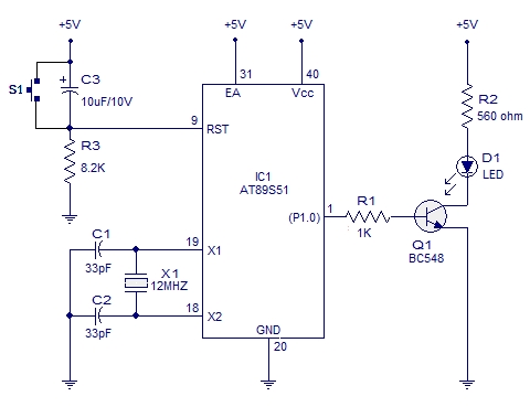 When P1.0 goes low the transistor goes to cut off and the LED extinguishes. The transistor driver circuit for the LED can be avoided and the LED can be connected directly to the P1.0 pin with a series current limiting resistor(~1K). The time for which P1.o goes high and low (time period of the LED) is determined by the program.
Program.
START: CPL P1.0
       ACALL WAIT
       SJMP START

WAIT:  MOV R4,#05H
WAIT1: MOV R3,#00H
WAIT2: MOV R2,#00H
WAIT3: DJNZ R2,WAIT3
        DJNZ R3,WAIT2
        DJNZ R4,WAIT1
        RET
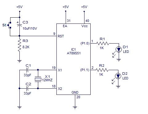
Blinking 2 LED alternatively using 8051.
This circuit can blink two LEDs alternatively. P1.0 and P1.1 are assigned as the outputs. When P1.0 goes high P1.0 goes low and vice versa and the LEDs follow the state of the corresponding port to which it is connected. Here there is no driver stage for the LEDs and they are connected directly to the corresponding ports through series current limiting resistors (R1 & R2).
For more detail: Blinking LED using 8051