
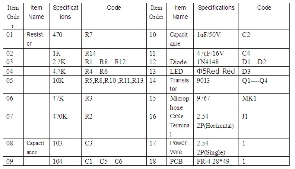
Description
Package name: clap switch kit
Kit Model: PSK-1
Operating voltage: 5V
PCB size: 28 * 49mm
How it works:
Q1 and Q2 composed of two audio amplifier circuit, the audio signal is accepted by the MK1 C1 is coupled to the base of Q1 pole, amplified and fed directly from the collector to the base of Q2 to a negative square wave at the collector of Q2, with to trigger the bistable circuit. R1, C1 circuit frequency response is limited to about 3kHz to high sensitivity range.
 The power is turned on, the state of the bistable circuit Q4 off, Q3 saturated, D3 does not shine. When MK1 received control signal, and a negative square wave output after two enlarged, negative spikes through D1 add to the base of Q3, the circuit rapidly flip, D3 is lit after differential processing. When MK1 again connected to the control signal, the circuit and flipped, D3 is off. Circuit board reserved for the terminal J1 access outside the control equipment and other devices through the J1 connector relay voice. (Then relays required at both ends of the relay coil anti and a diode)
Principle of Circuits
The circuit is maily composed by audio frequency and bistable tigger circuit.
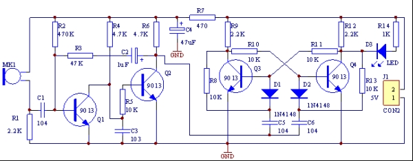
Q1 and Q2 form the secondary amplifier circuit. Audio signal which accepted by MK1 enters to Q1 base through the coupling of C1, and enters to Q2 base through collector directly after amplified. And it will obtain a negative square-wave which used to trigger the bistable circuit from Q2's collector.
For more detail: Clap Switch Suite/Electronic Production/DIY Kits