
Bi-polar stepping motors use only two coils and are easily recognized because they only have four wires. Most unipolar steppers can be used in bipolar mode by ignoring the two centre taps. Because bi-polar stepping motors produce the rotating magnetic field by reversing the current in both coils, controlling them is much more complicated than controlling their unipolar cousins.
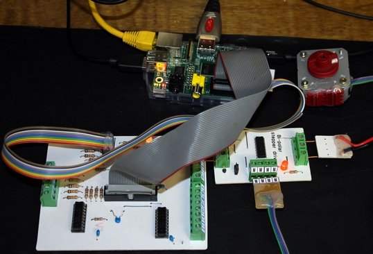
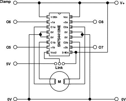
My circuit makes use of a SN754419 dual h-bridge chip, which takes all the hard work out of designing an interfacing circuit. As can be seen in the circuit diagram below, this project merely connects the chip to the relevant terminals. In fact, the board is so bare that I added a power ON LED out of pure embarrassment. I run my motor at 5V. If you use a motor with a higher voltage, you have to split the supply via the link and provide a separate 5V control voltage for the chip. The motor supply will then be connected to pin 9 and the logic positive to pin 8.
Below is a suggested PCB layout. Notice that the four centre earth pins also serve as a heat sink. This of course explains the large copper area in the centre of the pcb.
The program
My program drives the motor in both directions at nine different speeds. It allows both half step and full step mode.
 It uses GPIO lines 24,23,18 and 15. If your set-up uses different GPIO pins say a,b,c,d, change line 1250 thus:
1270 DIM Port%(5) : Port%()=15,24,23,18,15,24
1270 DIM Port%(5) : Port%()=,a,b,c,d,a
I am assuming of course that your arrangement a, b, c, d is the correct sequence.
For more detail: Driving a bi-polar stepper motor with the SN754410NE double H-bridge and a Raspberry Pi