
I’m in the process of building a home automation controller using my Raspberry Pi, and I figured it would be cool if it could display the current song and artist on my Pandora player. There were many options for a display — I could go with an LCD, an OLED, etc. I figured just to be different I would try a VFD display. VFD stands for “Vacuum Fluorescent Display”. VFDs are an older technology that has existed since the early 1960s. They differ from LCDs in that LCD displays typically have a backlight whereas a VFD emits light directly, in a similar manner to how a fluorescent light works. They often have a blue/green character color.
The first thing to do was to select an appropriate display. I settled on a Noritake CU16025-UW6J. This is a 2×16 character display that interfaces via SPI or Parallel. Using an SPI interface only consumes three or four of the pi’s pins depending on how you wire it. Minimizing GPIO use is always nice. I was able to pick up this display for $35 on ebay.
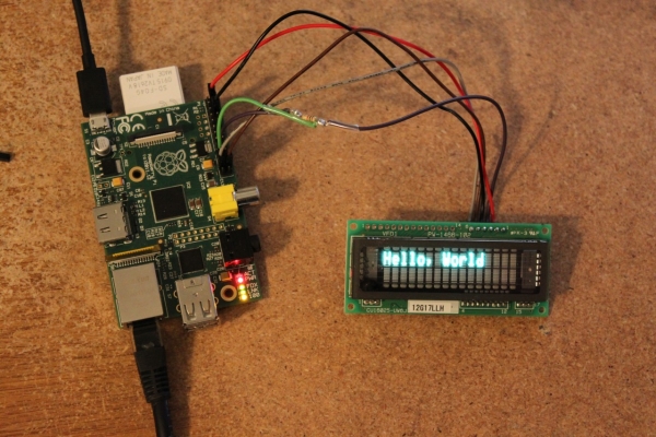 You’ll notice the display module has two headers. On the left there’s a 14-pin header (CN3) that’s used for parallel interfacing. On the right is a 6-pin header (CN1) that’s used for serial interfacing. We’ll be using the 6-pin header exclusively. On the back there is also a jumper, JP6, that you’ll need to populate in order to use the display in serial mode. Soldering JP6 was a little bit tricky as you have to solder it from the back of the board (I pushed the insulator on the header all the way to the top, soldered the header, and then pushed the insulator down).
Wiring
Click the diagram above to get a larger, more readable version. Note that we’re viewing the module from the back side, so pin 1 of CN1 is to the left and pin 6 is to the right. The VFD display requires two pins for power (+5V, GND) and three pins for IO (SI/SO, SCK, STB). The connections are:
| VFD Module> | Raspberry Pi | Notes |
|---|---|---|
| 1 | 2 | +5V |
| 2 | 19, 21 | SI/SO, use resistor on pi pin 19 |
| 3 | 6 | GND |
| 4 | 24 | STB / Chip enable |
| 5 | 23 | SCK |
Note the resistor inserted on the connection to Raspberry Pi ping #19 (MOSI). The reason for this is that we’re interfacing a 3-pin SPI device to a 4-pin SPI device. Pin #2 on the VFD is biderectional — sometimes it’s used to send data while other times it’s used to receive data. The Pi on the other hand has a dedicated send pin (19) and receive pin (21). If we ever entered a state, perhaps due to a programming error where the pi and the VFD were both outputting to the same pin with different values, a high amount of current could flow and the GPIO could become damaged. Thus the resistor.
I read several different web references on which resistor to use, with recommended values from 470 ohm to 10k ohm. I chose a 1K ohm resistor as that seemed sufficient to limit any current flow.

Setting up the Pi
Now we need to configure the pi to enable the SPI driver. Here’s a whole bunch of stuff to run:
# make sure the spi driver will be loaded

sudo emacs /etc/modprobe.d/raspi-blacklist.conf

(remove bcm2708-spi)

sudo reboot

# update our distro and install python development tools

sudo apt-get update
sudo apt-get -y install python-dev

# now let's build and install the python-spi library

mkdir python-spi

cd python-spi

wget https://raw.github.com/doceme/py-spidev/master/setup.py

wget https://raw.github.com/doceme/py-spidev/master/spidev_module.c

wget https://raw.github.com/doceme/py-spidev/master/README.md

wget https://raw.github.com/doceme/py-spidev/master/CHANGELOG.md

sudo python ./setup.py install
Note that this is for a somewhat dated Raspbian running on one of my old B models. For a newer raspian you might want to run raspi-config and use the advanced options to enable the SPI driver instead of editing /etc/modprobe.d/raspi-blacklist.conf.
Now we should have a raspberry pi with the SPI module being loaded automatically, and the python library installed.
For more detail: Interfacing a VFD display to the raspberry pi