
Raspberry Pi
Along came the Raspberry Pi and I noticed that it had a GPIO (General Purpose Input Output) interface. Ok I have to admit – I didn’t really know what that was until I read up on the Raspberry Pi and reports were saying it was designed for the novice to connect to and programme. I’m not really a novice (can program in PHP, VBscript/VBA) I thought, how hard can it be?
I’ve played with Linux for the last 12 years or so – so armed with that knowledge I joined the queue for my Raspberry Pi.
After the 6 weeks wait it arrived and after a few months (waiting for a spare moment) I set about solving my doorbell issue.
EEEEK! I thought it would be simple – just Google
Raspberry PI doorbell
and do what it says – I hit a brick wall – there are a few sites I found where people had done it but there was no code – no instructions. I joined a couple of forums and asked people how to do it – They just said “keep reading the forums”.
Anyway – I finally worked it out through butchering other project’s code that I found on the web.
Here I want to share that info so that you, the reader can do it too.
Raspberry Pi Hardware
To start with you need some extra bits of hardware:
Breadboard – this is a piece of plastic with holes in it where you can connect wires together to form circuits – the rows are connected, so where you want to connect wires together, you just plug them into the same row.
you can get them from http://www.fastestpc.co.uk/product.php?p=158057511 for £3.69
Jump Wire kit – You also need some wires. These kits come with various lengths of wire – you can of course cut them down if you want (though I didn’t bother).
Adafruit Pi Cobbler Breakout Kit for Raspberry Pi – I got this from Ebay too
http://adafruit.com/products/914
Note: You don’t actually need this – you could just connect to the breadboard directly from the GPIO Pins – but you will need cables with the small sleeves on them.
Adafruit Pi Cobbler Breakout Kit for Raspberry Pi – I got this from Ebay too
http://adafruit.com/products/914
Note: You don’t actually need this – you could just connect to the breadboard directly from the GPIO Pins – but you will need cables with the small sleeves on them.
Building the Breadboard to connect to the Raspberry Pi
I’ve never done any electronics before but I do have a multi-meter and know roughly how to use it.
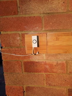
This breadboard came from Maplin and has the handy screw top connectors in Black, Yellow, Blue, Green and Red. Of course you can use any of them – I chose the Green and Red to connect to the actual doorbell using the bell wire that I was using for my rubbish wired battery doorbell.
Now expert electronics people may laugh at my wiring – but it literally takes 10 minutes to connect together.
This connects to a bog standard doorbell
Adafruit Pi Cobbler Starter Kit
I’ll start with the Ribbon cable connected Adafruit connector.
(Source: http://learn.adafruit.com/adafruit-pi-cobbler-kit/solder-it)
Here you can see The GND pin along the bottom row
(Source: http://learn.adafruit.com/adafruit-pi-cobbler-kit/solder-it)
The 3.3v power is on the other side of the connecter (far right) – is hidden in the top of the 3 pictures by the black connector wall.
Once this has been soldered together with the supplied pins as per http://learn.adafruit.com/adafruit-pi-cobbler-kit/solder-it which explains the process very simply, you pop that onto the breadboard. Remember that the rows of the breadboard are connected except where there is a channel between them – so in my image above the pins actually sit in columns V1 C and H and there is a channelled groove between F and G. If you were to put the board in A and F then it wouldn’t work as the 2 rows of pins would connect. Also you need some space to connect wires to it.
You connect the board as described above. It’s not important where you connect it as long as the points that you place the pins are in the correct rows corresponding to GND, 3.3v and the GPIO Pin you choose (I chose GPIO 23).
You can just connect the earth to one of the connectors of the door bell button and solder a resistor to the other side of the bell button pusher cable and the other end of it connected to 3.3v as well as GPIO23 – theoretically that should work but don’t hold me to it.
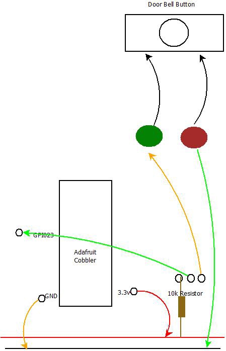
This is a simplified version of the one described at http://learn.adafruit.com/playing-sounds-and-using-buttons-with-raspberry-pi/bread-board-setup-for-input-buttons
As I only needed 1 button and didn’t bother with the momentary push-button switches (though I did buy these to test it).
So that’s the Breadboard setup and connected to the Raspberry Pi. Now the tricky bit.
Raspberry Pi PYTHON GPIO
I’ve never used Python – and to be honest I don’t really have a big desire to learn it. I’m not sure what I’d use that skills for, in any other project – but a lot of programming is cut and pasted from the web these days. So I followed the instructions at http://learn.adafruit.com/playing-sounds-and-using-buttons-with-raspberry-pi/overview and it all seemed to work. I could play an MP3 file if I pressed the button, BUT it was terrible – it would behave as if I pressed it 100 times.
I also had terrible trouble with it even accepting the button and just played the MP3 without pressing the button. In fact it even played the MP3 as soon as I ran the script, without the ribbon cable connected between the breadboard and Raspberry Pi.
For more detail: Raspberry Pi Doorbell (Python)