
Introduction
When I was little, I used to push the garage door button from inside the garage and then run out the garage while it's closing… carefully jumping over the sensor so I don't trip the safety mechanism. It was easy back then and a little fun. But nowadays, not so much. There are times when I wish I had a way to close (and open) the garage door remotely and preferably with something I always have on me… my mobile phone!
So this past Christmas, I looked into building something so I could use my smartphone as a garage door opener. I've read about the Arduino and Raspberry Pi platforms before that I believed would accomplish the task and, ultimately, I decided on the Raspberry Pi. The Arduino platform after some research and cost analysis would have cost more than the Raspberry Pi! That wasn't something I was expecting since the Raspberry Pi is more robust and a full-blown mini-Linux computer. The possibilities are really endless.
A wifi Raspberry Pi connected to a 2-channel relay connected to my actual garage door remote allows me to open and close my garage door with just a browser on my smartphone.
After only writing software for many years in web development, creating something that interacts with the real world was a special kind of excitement for me when I saw it work for the first time.
Below I'll go through the steps and the issues I ran into while working on this project.
Step 1 – Parts
Below is a list of the parts I gathered together to get started. Prices will most likely not be same.
- Raspberry Pi B+ Complete Starter Kit with WiFi Adapter (Raspberry Pi B Plus + WiFi Dongle + 8GB SD Card + Case + Power Supply + HDMI Cable – $60
- a 2-channel relay – $8
- female-to-female jumper wires – $8
- ethernet cable
- a LED to test out the GPIO pins
- solder gun + solder (if hooking it up to a garage door remote)
- usb keyboard and mouse, HDMI monitor and HDMI cable. These are only necessary for the initial setup until you have the Pi networked after which you can go headless and SSH in from another computer.
Total cost: $76 since I had a few of the needed parts already.
Step 2 – Setup the SD card
I followed this guide to setup the SD card with NOOBS and bootup the Pi for initial setup.
Raspberry Pi Quick Start Guide
Step 3 – Setup the Pi and Install Raspbian
Setting up the Pi is pretty easy. Just hookup the HDMI cable, usb keyboard and mouse, plug in the SD card prepared in step 2, and finally turn on the Pi by plugging in the micro-USB power supply. This should bootup NOOBS and step you through the process to install an OS. The one you want for this project is Raspbian. Complete the Raspbian setup and you should have a working Pi at the end.
It's at this step that I encountered my first problem. I used the keyboard and mouse I had from my main PC rig, a Logitech G110 keyboard and a Logitech G9 mouse. After NOOBS booted up, I found I couldn't type or control the mouse. The problem turned out to be the USB ports on the Pi doesn't provide enough power for the keyboard and mouse. You can get around this issue by using a powered USB hub.
Step 4 – Setting up Wifi
You can skip this step if you're going to leave the Pi connected with ethernet cable. In fact, I recommend skipping this step until the end to simplify things.
I didn't want the Pi to be tethered by an ethernet cable so I proceeded to try and set it up with the USB wifi dongle. This turned out to be probably the hardest part of the project. I followed a bunch of guides I found but none of them worked for me. It's not that the dongle wasn't supported by Raspbian, but I couldn't get it to connect to my wireless router. After much headache and tinkering around, I finally fixed the problem. You can read about the details in my wifi setup guide.
After using this setup for a few weeks, I found the Pi to be inaccessible after a period of inactivity. This turned out to be a power savings feature where the wifi component is turned off.
I did the following to disable this feature:
sudo vim /etc/modprobe.d/8192cu.conf
Add the following:
 # Disable power management
 options 8192cu rtw_power_mgnt=0
Step 5 – Experiment with the GPIO on the Pi
What makes the Raspberry Pi so interesting to me are the GPIO pins which allow the Pi to communicate and control other peripherals. I found this excellent guide to get a basic understanding of the GPIO.
My first test with the pins was to simply connect a LED I had lying around and see if I could get it to light up.
LEDs generally have 1 leg which is longer than the other. The longer leg should be the + (positive) connection. If the LED doesn't have a visible difference in the leg lengths, then you can look at the top of the LED and you should see 2 small pieces of metal. The smaller side is the + connection. Here's a good diagram.
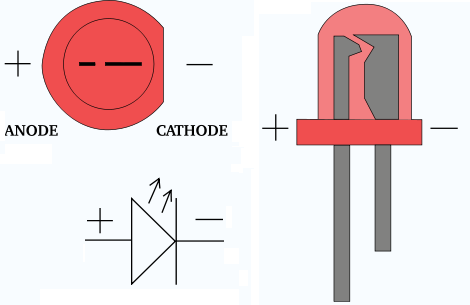
Start by connecting a jumper wire to GPIO pin 1 for the 3.3v power and another wire to the GND at pin 6. [photo]. This should light up the LED. Yay! Ok, admittedly, that's not terribly exciting. It's just a light.
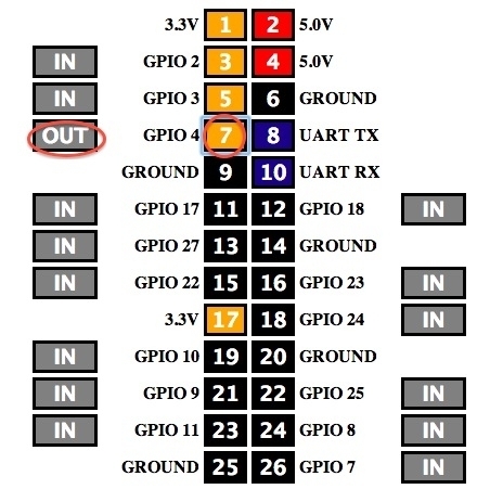
Next, unplug the jumper wire from pin 1 and connect it to pin 7 which is GPIO4. The LED should be unlit for now. To control the GPIO ports, there are a ton of different choices. Just google for Raspberry Pi GPIO but I started with this wonderful framework called WebIOPi.
Follow the WebIOPi installation guide and run this:
$ sudo webiopi -d -c /etc/webiopi/config
That should start the webiopi server on port 8000. You can then access the webiopi page in a browser at http://192.168.1.60:8000. Of course, replace 192.168.1.60 with the IP of your Pi.
You should see a GPIO Header link on the main page. Click that link and you will be able to control the GPIO using a web UI which looks like the board header.
Click the ‘IN' box to the left of GPIO4 to toggle that to say ‘OUT'. Then try clicking on the box to the right of GPIO4 with the number 7 in it. If everything's working then you should now be able to on/off the connected LED.
Toggling the LED on/off was super exciting for me. It was the first time I had built anything on a computer that could interact with the real world. The Internet of Things as they say. For better or worse, it's coming and probably sooner rather than later.
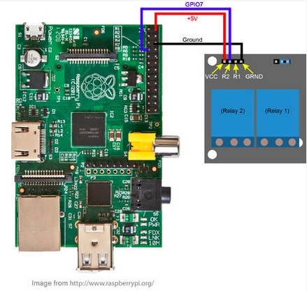
Step 6 – Wiring the 2-Channel Relay
Now it's time to replace the LED with the relay. Remove the LED from the jumper wires and reconnect the wires according to this drawing below.
It was at this point that ran into my next problem. Every time I connected the relay and switched GPIO4 to ‘OUT', the Raspberry Pi would crash and I'd have to unplug/reboot it. It took me awhile to figure out that the power supply I was using wasn't supplying enough power for everything. Apparently, powering the relay pushed it over the edge. The power supply I was using was from an old Motorola smartphone that was rated to only output 750ma. After I switched that out to another power supply I had lying around with 1850ma, I no longer had stability issues with the Pi.
You can test your connections now by going back to the WebIOPi page and toggle GPIO4 on/off and you should be able to see a small light on the relay respond accordingly. If you do, then that's a good sign. It means you are able to control the relay to open and complete a circuit.
For more detail: Raspberry Pi Garage Door Opener with GaragePi