Raspberry Pi Robot – Connecting the H-Bridge & Motors

For this project we will be using four of the Raspberry Pi’s GPIO pins, two per motor.  In the diagram below you will see a diagram of a L298N (hopefully yours will look the same or very similar).  Each motor will have two wires running from them, this will allow us to connect them to “output A” and “output B”.
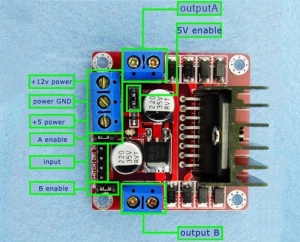
Raspberry Pi Robot – Connecting the H-Bridge & MotorsWe will be connecting our battery pack up to the +12v power terminal since we will be providing the H Bridge Motor Controller with 6v from the battery pack that is in our Zumo Chassis.  We will also want to run the ground from the battery pack and also from the Raspberry Pi to the ground terminal on the H Bridge Motor Controller.

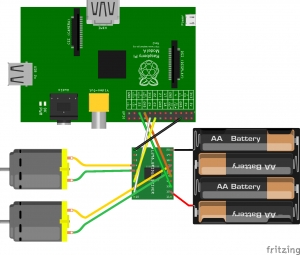
Finally we want to run our input cables from the Raspberry Pi GPIO ports to the four input pins of H Bridge Motor Controller.  I have done them in the following order :

Raspberry Pi Robot – Connecting the H-Bridge & Motors Diagram

Pin 1: Yellow Cable should be GPIO 16

Pin 2: White Cable should be GPIO 18

Pin 3: Green Cable should be GPIO 21

Pin 4: Orange Cable should be GPIO 19

This is all there really is to connecting your motors and motor controller up ready for coding our Raspberry Pi robot to move!


For more detail: Raspberry Pi Robot – Connecting the H-Bridge & Motors


About The Author

Ibrar Ayyub

I am an experienced technical writer holding a Master's degree in computer science from BZU Multan, Pakistan University. With a background spanning various industries, particularly in home automation and engineering, I have honed my skills in crafting clear and concise content. Proficient in leveraging infographics and diagrams, I strive to simplify complex concepts for readers. My strength lies in thorough research and presenting information in a structured and logical format.

Follow Us:
LinkedinTwitter

Leave a Comment

Your email address will not be published. Required fields are marked *

Scroll to Top