Relay I/O Board is widely used in applications of smart home project. In this article, I will detail how to control the Relay I/O board using Raspberry Pi with Raspberry Pi Universal Expansion Board via internet. The codes and schematic diagrams used in this article was listed at the end of this article.
Part I: Hardware
1. Pin Mapping
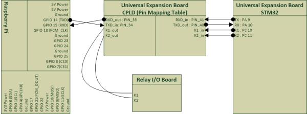
The CPLD on the Raspberry Pi Universal Expansion Board can be used to map pins between modules. For this project, we want to map pins as following diagram Fig.1.

|
1
2
3
4
5
6
7
8
9
10
11
12
13
14
|
module RS232(RXD_in,TXD_in,RXD_out,TXD_out,K1_in,K1_out,K2_in,K2_out);input RXD_in, TXD_in,K1_in,K2_in;output RXD_out,TXD_out,K1_out,K2_out;assign RXD_out = RXD_in;assign TXD_out = TXD_in;//assign pins for relays K1 and K2assign K1_out = K1_in;assign K2_out = K2_in;endmodul |
We can flash the design into the CPLD right now.
2. STM32 Configuration
Creating a new .c source code file RelayIOBoard.c as the driver of the Relay I/O board:
|
1
2
3
4
5
6
7
8
9
10
11
12
13
14
15
16
17
18
19
20
21
22
23
24
25
26
27
28
29
30
31
32
33
34
35
36
37
38
39
40
41
42
43
44
45
46
47
48
49
50
51
52
53
54
55
56
57
58
59
60
61
62
63
64
|
/*Driver for Relay IO board*/#include < stm32f10x.h>#include < stdio.h>#define on 1#define off 0int k1_state;int k2_state;void Relay(int relay_num, int on_off){ switch( relay_num ) { case 1: //For K1 which is controlled by the PC10 if(on_off == on) { GPIO_SetBits(GPIOC, GPIO_Pin_10); k1_state = on; } if(on_off == off) { GPIO_ResetBits(GPIOC, GPIO_Pin_10); k1_state = off; } break; case 2 : //For K2 which is controlled by the PC11 if(on_off == on) { GPIO_SetBits(GPIOC, GPIO_Pin_11); k2_state = on; } if(on_off == off) { GPIO_ResetBits(GPIOC, GPIO_Pin_11); k2_state = off; } break; }}void Get_Relay_States(void){ if(k1_state == on){ printf("k1on\r\n"); } else{ printf("k1off\r\n"); } if(k2_state == on){ printf("k2on\r\n"); } else{ printf("k2off\r\n"); }}void Relay_init(void ){ Relay(1,off); Relay(2,off); k1_state =off; k2_state =off;} |
We need to add following commands to the Shell() in CommandShell.c:
|
1
2
3
4
5
6
7
8
9
10
11
12
13
14
15
16
17
18
19
20
21
22
23
24
|
//Command K1 onif(IsStringMatch(Command,"k1on",Counter)){ Relay(1, 1); printf("k1on\r\n"); }//Command K1 offif(IsStringMatch(Command,"k1off",Counter)){ Relay(1, 0); printf("k1off\r\n"); }//Command K2 onif(IsStringMatch(Command,"k2on",Counter)){ Relay(2, 1); printf("k2on\r\n"); }//Command K2 offif(IsStringMatch(Command,"k2off",Counter)){ Relay(2, 0); printf("k2off\r\n"); }//Command krs, get relay statesif(IsStringMatch(Command,"krs",Counter)){ Get_Relay_States(); } |
For convenience, the Firmware STM32_Relay_1.0.hex needs to be flashed into the MCU. The Firmware will host a Command Shell on UART1. It also includes the driver of the Relay I/O board.
3. Testing
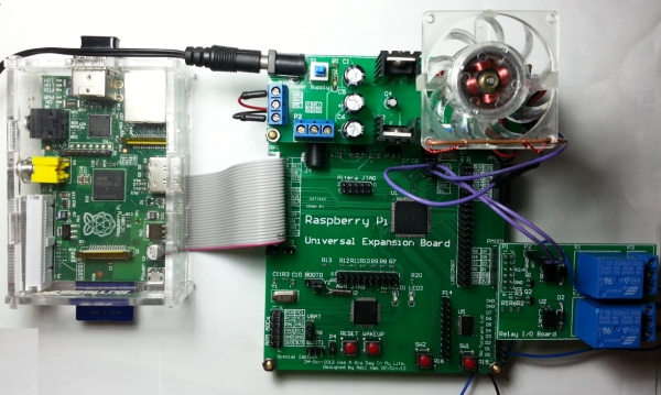
Connecting Relay I/O Board to the Pmod1 socket on the Raspberry Pi Universal Expansion Board. A cooling fan may be controlled by the relay as following figure.
For more detail: Raspberry Pi with Relay I/O Board


