
Roomberry is a surveillance robot based on Roomba using a Raspberry Pi Zero W and a camera module.Years ago I started doing some tests to control a Roomba remotely using an Arduino One with a RN-VX WiFly module.
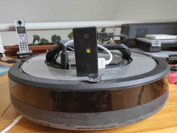
Last month I decided to revitalize the idea but with a new objective: to turn the Roomba into a surveillance robot with the ability to take photos and videos. The first idea was to keep using the Arduino as microcontroller employing an Arducam module to capture pictures. However I quickly found that the image processing capacity of Arduino was too limited for my interests. The second option was to change the platform and use a Raspberry Pi Zero W with a camera module. This alternative meant some challenges, specially regarding powering but also offered more possibilities. In this post I will explain how to build Roomberry, a surveillance robot based on Roomba using a Raspberry Pi Zero W and a camera module.
A demonstration of Roomberry’s capabilities and the web interfacedeveloped to interact with it can be seen in the following video.
iRobot Roomba
iRobot’s Roomba offers an Open Interface (OI) to interact with the robot though a mini DIN connector. The OI is a software interface designed for Roomba creator 2 (an adaptation of serie 600). However, it is fully compatible with series 500 and 700 too. There are nevertheless some bugs depending on the platform and the firmware version used. The software interface lets you manipulate Roomba’s behaviour and read its sensors. A full description of its capabilities can be found in this document.
Mini DIN Connector
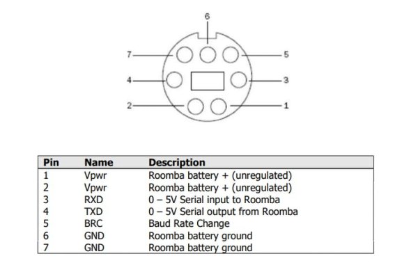
The Roomba mini DIN connector is located in the front right side of Roomba serie 700 and has 7 pins. Its position varies slightly in the series 600, whose location is in the rear right side of Roomba, under a snap-away plastic guard. Mini DIN 7 male connectors are complicated to buy, however the more common mini DIN 8 pin male connector is also compatible.
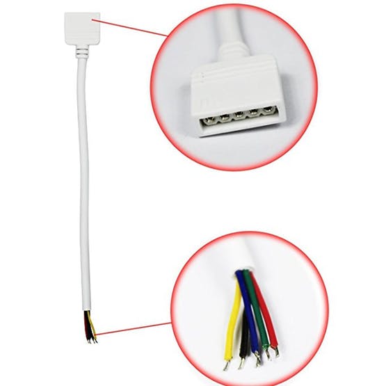
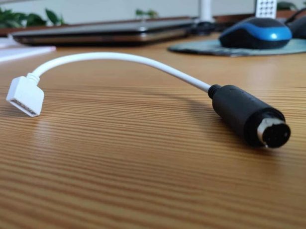
To ensure a smooth and reliable connection/disconnection of the port, I soldered a 5 pin cable (designed for LED strips) with a female connector to a mini DIN 8 pin male connector using pins 1-2 (power), 6-7 (ground), 3 (RxD), 4 (TxD) and 5 (BRC). However, as commented later on, the power/ground connection were finally not needed. The resulting cable can be seen in the following pictures.
Roomba Serial Port
To use the OI, the commands should be sent though a two-way serial communication created in mini DIN 7 pins 3 (RxD) and 4 (TxD). This UART port works at TTL levels (0 – 5 V). This voltage is perfectly fine for microcontrollers using 5V logic, like most Arduino boards. However it is not good for those with lower voltage logic levels (like the Raspberry Pi).
In theory, pin 3 (RxD) will take 3.3 V as the high logic level. But the Roomba will output 5V on its pin 4 (TxD), which may damage the Raspberry Pi Zero. To keep the hardware safe a logic level shifter should be used. The simplest way to do this is with a resistor divider, as already implemented in my previous project Calduino, but this may not work at high speeds (Roomba’ serial port works at 115200 bauds).
Instead of that, an active level shifter is preferable. If you want to build your own circuit, use the field effect transistor AN10441 as explained here. A much easier option is to use one of the existing bi-directional logic level converters such as this one from Adafruit. This device can manage up to 4 signals and safely step them down from 5V to 3.3V. At the same time it steps signals up from 3.3V to 5V.
Powering Raspberry Pi From Roomba
There are a few alternatives to provide power supply through Roomba’s battery:
Powering From the Mini DIN 7
The mini DIN 7 provides an unregulated direct connection in pins 1/2 (Vcc) – 6/7 (Gnd) to Roomba’s battery. The connection is limited to 200 mA though a PTC resettable fuse. It offers a voltage between 20.5 and 10V, limited to 0.2A with a power of 2W. The continuous draw from these two pins together should not exceed 200 mA. Drawing a peak greater than 500 mA will reset the fuse.
A Raspberry Pi Zero W should be able to work using this supply. The Raspberry Pi Foundation rates the typical bare-board active current consumption in 150 mA. This benchmark places it between 120 mA in idlestatus and 180 mAunder stress (playing FullHD video, for instance). However, here the extra consumption of the camera is not considered. According to my measurements, the camera (I use this one, with the same sensor as version 1 official Pi camera) increases the power consumption to more than 300 mA, with peaks of 450 mA. During my test the fuse was tripped several times while recording videos.
As a conclusion, the existing thermofuse dismisses the use of this connection to power the Raspberry Pi Zero W. I have not been able to find out if it is possible and safe to remove the fuse from the board without damaging other components.
Powering from an external power bank
There are a few alternatives to avoid this fuse limit. On the one hand, the easier solution would be to use a power bank to provide external power to the Raspberry Pi Zero. However, it will require the user to charge it periodically. Another option would be to design a serial connection between the mini DIN 7 power supply and the power bank. With a couple of electronic components it should be possible to use the Roomba battery to charge the power bank. To simplify my design I decided to avoid the use of any additional sources of power.
Powering From the Battery
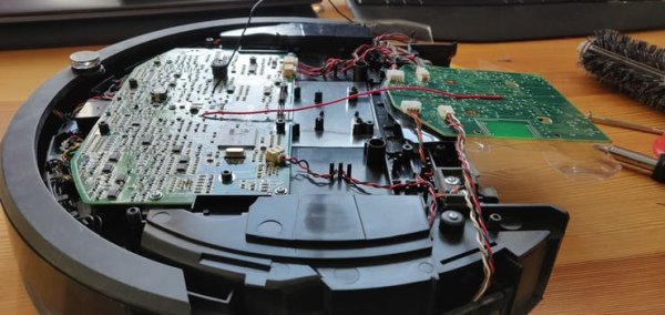
I finally decided to bypass the fuse by building a direct connection to thebattery pack. The counterpart of this option is that you will have to partially disassemble the robot. In Roomba series 600 there are two big pads directly connected to the battery pack below the dock button. In Roomba series 700/800 you will have to disassemble a couple of components more. Have a look at the following video until minute 6 to see, step by step, how to access your robot’s motherboard. Once done, just solder a couple of cables to the battery pad as shown in next pictures.
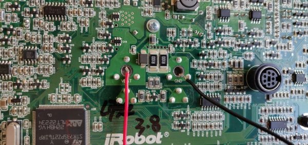
These cables will provide a direct connection to the battery not limited by any fuse. They supply between 20.5 and 10V, depending on the battery charging level. However, the Raspberry Pi Zero W needs a regulated 5 V source of power. To reduce the voltage an step down is used. There are a lot of options to do this ranging from the use of a cheap linear regulator (such as the 7805 TO-220) with a couple of capacitors to installing a switching regulator.
Due to its higher efficiency, and considering that it will be always connected, I would advise to use/buy a good quality (avoid China imitations) step-down switching regulator. I have used Pololu D24V5F5 buck regulator which takes an input of up to 36 V and reduces it to 5V for a maximum output current of 500 mA. Its efficiency is rated between 85% and 90% and has a very low dropout. You can also use an UBEC (Universal Battery Elimination Circuit), such as the one commonly used in RC world. I placed my voltage regulator in a free space situated in the centre – right side of the robot.
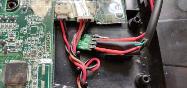
The connections were properly protected with heatshrink and the D24V5F5 module was covered with isolating plastic (I did not take any photos of this). I soldered the module output to a micro-USB cable, which allows me to connect it directly to the Raspberry Pi Zero W power input.
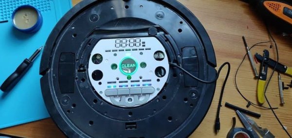
Using a rotating drilling tool and sandpaper I created a little notch in Roomba’s upper cover to allow a clean outlet of the micro USB cable as can be seen in the following picture.
Roomba OI Modes
The Roomba OI has four operating modes: Off, Passive, Safe, and Full.
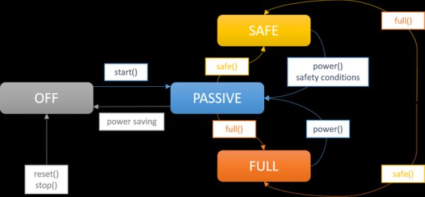
Off Mode: After a battery change or when first powered, the OI is in off mode. In this status the Roomba listens to the port at the default baud rate (115200) waiting for anstart command. The commands reset and stop can be sent at any time and will turn OI also in off mode.
Passive Mode: Once an Start command is sent, Roomba enters passive mode. In this status you can request and receive sensor data using any of the sensor commands. However you cannot change the current command parameters for the actuators (motors, speaker, lights, low side drivers, digital outputs). Roomba will enter passive mode too if one of the cleaning mode commands (Spot, Clean, Seek Dock, etc.) is sent.
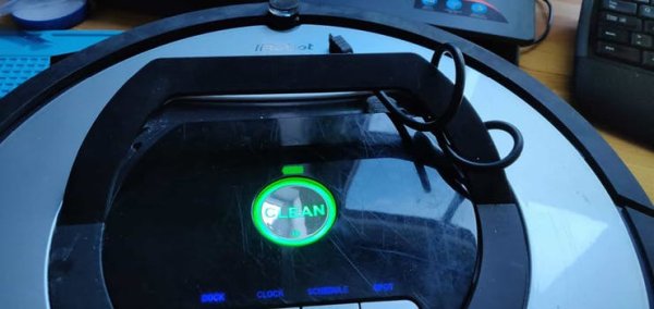
While in passive mode Roomba will go into off mode after five minutes of inactivity to save power and preserve battery. According to iRobot documentation, sleep can be disabled just pulsing the BRC pin low periodically before these five minutes expire. Each pulse should reset this five minutes counter. In the tests that I have performed (with a Roomba 780), pulling low the BRC will only wake up the robot, but it will not prevent it from going to power saving mode. The robot will beep when it wakes up (if it is not being charged in the dock station).
Safe Mode: Roomba will enter in Safe mode if the Safe command is sent. Safe mode gives you full control of the robot and turns all motors and LEDs off. However, if a safety-related condition is not met, the robot will turn automatically into passive mode. Those safety conditions are: detection of a cliff while moving forward, wheel drop and charger connection. In this mode Roomba will not charge (although being at the dock) and will not save power by switching to off mode after 5 minutes of inactivity. This point is very important: you can end up draining the robot’s battery and damaging it if you don’t switch to passive or off mode.
Full Mode: When you send a Full command to the OI, Roomba enters Full mode. The robot will behave exactly as in Safe mode, but it will not consider the safety-related conditions previously commented so be aware of the risks!
Battery precautions: As commented, in Passive mode, Roomba will sleep after 5 minutes of inactivity to preserve battery power. In Safe and Full modes, Roomba will never sleep, and if it is left in this state for an extended period of time, it will deeply discharge its battery, even if plugged into the charger. The charger will power Roomba in all modes, but it will not charge the battery in Safe or Full mode. It is important to return Roomba to Passive or Off mode once a job is done and/or when battery level is low in order to protect it.
Raspberry Pi Zero W
The Raspberry Pi Zero W is an updated version of the Raspberry Pi Zero with wireless LAN and Bluetooth. The model includes a 1 GHz single-core CPU, 512MB of RAM, mini-HDMI, a micro-USB OTG port, micro-USB for power, 40-pin header, composite video, reset headers, a camera connector, as well as the new wireless features. It uses wireless chip Cypress CYW43438 that supports 802.11b/g/n Wi-Fi (2.4GHz-only) and Bluetooth 4.0 (same chip as Raspberry Pi 3 Model B). I bought it in Pimoroni with headers (not soldered) and adapters for 16€.
Camera
The Raspberry Pi Zero W CSI camera connector is smaller than the Pi 3 one. If you already have a camera, you will have to buy an adapter to use it. Otherwise, I would recommend to buy this camera module, which incorporates a 5MP sensor (same as version 1 official Pi camera) and can record video at 1080p. It costs 18€. I chose the wide angle camera with IR cut. I know that I will not be able to see anything at night but the use of IR LEDs will increase the energy consumption, which I wanted to keep low. You can always use Philips HUE lights to remotely control your home lights.
Powering Raspberry Pi Zero W
There are a couple of considerations to be made regarding Pi Zero’s power supply. First of all, and unlike larger models, the Pi Zero does not have any regulation or fuse to protect it from over-voltage or current spikes. It means that you should supply a stable source of power with 5 V. The source of power can be connected to the right side micro USB (Pwr In) or to the 5V pin on the GPIO header. Both of them are the same line. Be sure that if an incorrect voltage is applied or a current spike occurs in the line, you will probably damage your Raspberry Pi permanently.
As it has already been commented, consumption peaks of 400 mA with the camera connected have been measured while running stress tests. The Raspberry Pi Foundation recommends a power supply of at least 1.2 A. However, the 0.5 A provided by the buck regulator have been enough for me. Until now I did not found any problems related with the power supply.
Reducing Power Consumption
Considering that the Raspberry will run from Roomba’s battery, it will be interesting to reduce the power consumption as much as possible. For instance, knowing that the Pi Zero will run headless (without a monitor connected) and will only be accessed through SSH, there is no need to power the display circuitry. Disabling the HDMI port can save up to 25 mA. To do so, just run /usr/bin/tvservice -o (or with -p to re-enable). I have placed a short script in /etc/rc.local which checks if the HDMI cable is connected or not and disables the HDMI port accordingly.
# Get the current video output type and strip away the unimportant bits
video=“$(tvservice -s | sed “s/^.*\[\([^ ]*\) .*$/\1/” )“
if [ “$video“ != “HDMI” ]; then
printf “HDMI not detected. Turning off.\n”
tvservice -off > /dev/null
else
printf “HDMI detected.\n”
fi
Another way to reduce the power consumption is disabling the LEDs of the Pi. The Raspberry Pi Zero has only one, the activity LED, that blinks every time the SD card is accessed. Its consumption is approximately 5 mA. To totally disable it add this lines in your /etc/rc.local file:
# Set the Pi Zero ACT LED trigger to ‘none'
echo none | sudo tee /sys/class/leds/led0/trigger
# Turn off the Pi Zero ACT LED
echo 1 | sudo tee /sys/class/leds/led0/brightness
You can also do this by editing the /etc/config.txt file:
# Disable the ACT LED on the Pi Zero
dtparam=act_led_trigger=none
dtparam=act_led_activelow=on
I am not sure if this will translate into a real consumption reduction, but as it will not be used, you can disable the bluetooth module of the Pi Zero by adding the following line to /etc/config.txt:
# Disable bluetooth on the Pi Zero
dtoverlay=pi3-disable-bt
Finally, try to reduce the software installed and running in the Pi Zero. For instance, use Raspbian lite instead of the desktop version and do not install extra software unless you really need it. The more processes running on your machine, the more consumption it will have.
Other Considerations
- It will be very useful to build a reset button in the Pi Zero. This way you will avoid having to disconnect and connect the power supply every time you want to restart the system. To do so, you only have to connect the Raspberry’s holes marked with run with a momentary switch. I have used one of this from Sparkfun.
- You will require a new and fresh MicroSD card with Raspbian Stretch lite or newer. As explained in this post, I would recommend using a card as large as possible. Although the configuration applied here tries to reduce the disk writes, leaving plenty of free space ensures a longer life to the SD cards.
- This tutorial considers that the Raspberry Pi Zero used is running Raspbian Stretch headless. You can read in previous posts how to install Rasbian, create new users and connect using SSH.
Building Roomberry
Once all the pieces have been described, let’s see how to build and run Roomberry, your Raspberry interface with Roomba.
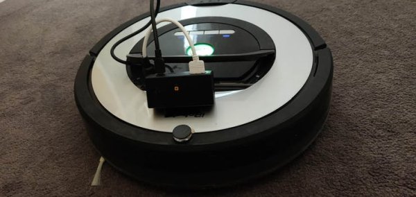
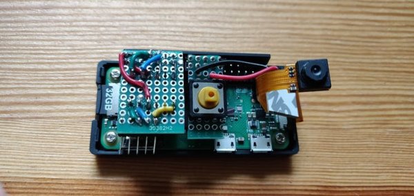
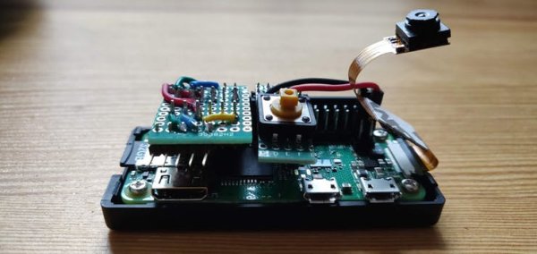
My objective was to encapsulate the components (Raspberry Pi Zero, camera module, logic level converter and switch button) in an stable case with easy access to all ports and SD card. The only option that I found, excluding printing my own 3D design, was this one. This case satisfies all the requirements and allows me to attach a HAT (Hardware Attached on Top), an add-on board with the couple of electronic components needed. The following image shows the PCB schema. Note that the Run pins are located in the Pi Zero and not in the HAT. To build it, a piece of a PCB Board of 12 x 10 pins will be enough. To cut the PCB I have used a rotary tool.
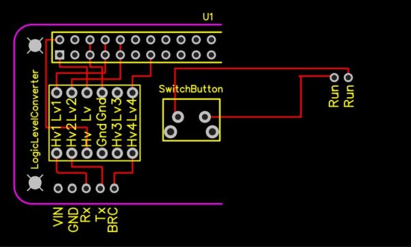
The logic level converter will need both high and low voltage, which can be obtained from GPIO (the Pi Zero includes a step down converter from 5 to 3.3 V named PAM2306AYPKE). I have placed the switching button in the middle of the Pi Zero, as it was an extension of the HAT. By doing so the button’s stem stands out the case so it can be pressed externally. You will have to drill a couple of holes in the case: one for the button steam and another (and bigger) hole for the camera. Moreover, I had to sand carefully the case’ space designed for the CSI connector to make room for a 180-degree turn of the cable. The following pictures show the results:
Configuring Raspbian Stretch
Before connecting Roomberry to the mini DIN 7 connector of the Roomba, a few configuration steps should be performed. Assuming that the Raspberry Pi Zero W is running the last version of Raspbian and is already set up headless.
Connect the micro USB power supply built previouslyto the Pi Zero. After a few seconds the system should be up and running. Open an SSH connection to your pi Zero.
By default the Pi’s serial port is configured to be used for console input/output. To communicate with Roomba though this port, the serial console login needs to be disabled. You can do it with raspi-configchoosing menu 5 – Interfacing options and P6 – Serial. Answer No to the question “Would you like to login shell to be accesible over serial?” and Yes to “Would you like the serial port hardware to be enabled?”. Do not restart the system yet. Alternatively you can also comment the console definition and add to the end of file /boot/config the following line:
#Find and comment console definition
#console=serial0,115200
...
enable_uart=1
If you have not done it yet, enable the camera module. Again, you can do it though raspi-config choosing menu 5 and P1 option. On the other hand, you can also edit file /boot/config and include these changes (disabling camera led is not required but recommended to save power):
start_x=1
gpu_mem=128
disable_camera_led=1
I am not sure which is the optimum quantity of RAM to assign as gpu_memory when the camera module is being used. Until now I have not found any “Out of resource” errors while operating with the camera, so I assume 128 Mb is a good choice.
Disable all swap and mount /tmp directory in RAM Disk with 50 megabytes of space. This location will be used to store ephemeral files, such as camera snaps and Roomba status files. Increase the commit time in etc/fstab to 30 minutes and include the noatime option in the SD partition. Find the commands in this post.
Now it is time to test if everything is working correctly. Turn down your Pi and connect the serial port to Roomba. Place the Roomba at the charging dock. Boot the system and check that everything is working as expected (and that the robot is not doing anything strange).
Test reading from serial port: I have used minicom to read the data sent by Roomba. To install it just type:
sudo apt-get minicom
Connect with the serial port of Roomba by doing:
minicom –b 115200 -o -D /dev/serial0
If your Roomba is charging you should see a text similar to following image reporting the charging state of the Roomba every second. Press CTRL + A and X to exit minicom.
Read More Detail :Roomberry Surveillance Robot: Roomba + Pi Zero + Camera