
Introduction
This tutorial will show you how to assemble, program, and access the Raspberry Pi Zero Wireless Pan-Tilt Camera.
Required Materials
You’ll need a microSD card, a sufficient power supply, and a micro-B USB Cable. We do not recommend the pre-installed NOOBS card, as it may not include a recent enough version of the Pi operating system to support the Pi Zero W.
Required Tools
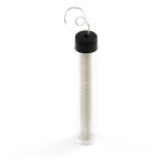
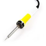
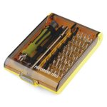
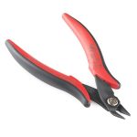
You’ll need a few tools to assemble this kit: just a standard soldering iron, solder, a small screwdriver, and a pair of side cutters.
Prepare the MicroSD Card
To prepare the microSD card, we need to:
- Download the latest Raspberry Pi Raspbian Jessie image.
- Create an microSD card that contains this boot image.
- Edit the “config.txt” file on the microSD card to enable the serial debug console.
- Create a “wpa_supplicant.conf” file on the SD card to enable WiFi.
Let’s walk through these steps in more detail!
Download the Latest Raspbian Jessie Image
You can find the image on the Raspberry Pi Foundation Website. It’s a fairly large download so go get a snack or play a game or something.
Burn the Image to an MicroSD Card
To write the image to the card, there exists an excellent utility for Mac/Linux/Windows called Etcher. Simply download and install it to your computer. Then select the image you downloaded earlier, the drive you want to install to (Etcher won’t let you install to anything but a removable drive, and if only one drive is available, it will select it automatically!), and click “Flash!”
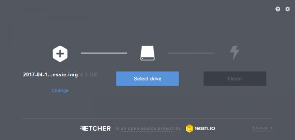
This is another long-ish process, requiring several minutes to complete. Once complete, the window will display a “Flash Complete!” message.

By default, Etcher “ejects” the card after it has created the image, so you’ll need to pull it out and reinsert it to get your computer to reload the disk.
Edit the “config.txt” File on the MicroSD Card
To continue, we’re going to need to edit a file on the microSD card. This file will be visible from any operating system, although on a Linux system it’s in a slightly different location.
On a Windows or Macintosh, the files will be loaded in the root directory of the microSD card, so when you open a window of the drive, you’ll see them directly. In Linux, the card will be mounted, and you’ll have to navigate to the “Boot” directory on the card to find the file we’re looking for.
Here’s a list of all the files in the directory of interest.
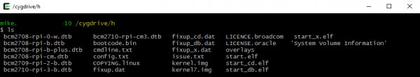
Click the image for a closer look.
Open the file “config.txt” in your favorite text editor (i.e. Notepad++, TextWrangler, ConTEXT Editor, etc.) and add this line to the very end:
enable_uart=1
Create a “wpa_supplicant.conf” File on the MicroSD Card to Enable WiFi
The last thing we need to do to prepare the microSD card is to create a “wpa_supplicant.conf” file on the card. This file contains the information needed for your local wireless network setup.
Create a new file using your favorite text editor. On Windows we recommend Notepad, as it provides WYSIWYG content and allows you to save a file with an arbitrary file extension. On MacOS, TextWrangler seems to be the easiest. For Linux, your default system text editor should be fine.
The contents of the file can be quite simple. Most likely, you can get away with something that looks like this:
network={
ssid=”YOUR_SSID”
psk=”YOUR_PASSWORD”
key_mgmt=WPA-PSK
}
Once added, modify the network ID and password for your WiFi network. Then save the file as “wpa_supplicant.conf” to the microSD card.
Important Note: On the on the “Save As…” screen for Windows users, you'll need to change the file extension type under the field “Save as type:” from “*.txt file” to “All files”. Then you will need to explicitly name the file “wpa_supplicant.conf”, or Notepad will automatically append “.txt” to the file name, breaking this functionality. See the image below.
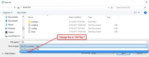
Some variation of this “Save as…” and removing the appended “.txt” suffix is necessary in Mac OS and Linux as well, but should be equally simple.
Pull the MicroSD Card and Insert It into the Pi Zero W
This is all we need to do in preparation of our first boot. You can now remove the card from your computer and put it into the Pi Zero W. Don’t power it up yet, though!
Hardware Assembly
To assemble the hardware, we need to:
- Solder headers to the Raspberry Pi Zero W.
- Solder headers to the Pi Servo Hat.
- Install the Pi Servo Hat on the Pi Zero W.
- Assemble the pan-tilt hardware and connect the servos to the hat.
Let’s walk through these steps in more detail!
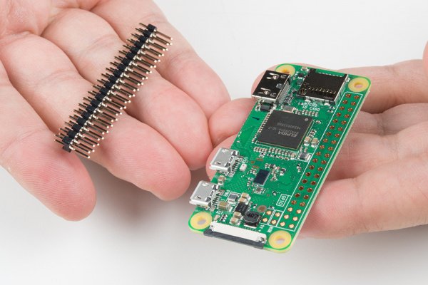
Solder Headers to the Raspberry Pi Zero W and the Pi Servo Hat
We recommend soldering the male header to the Pi Zero W and the female to the Pi Servo Hat. If you have any issues with soldering, please check out our learn to solder tutorial.
Assemble the Pan-Tilt Mechanism
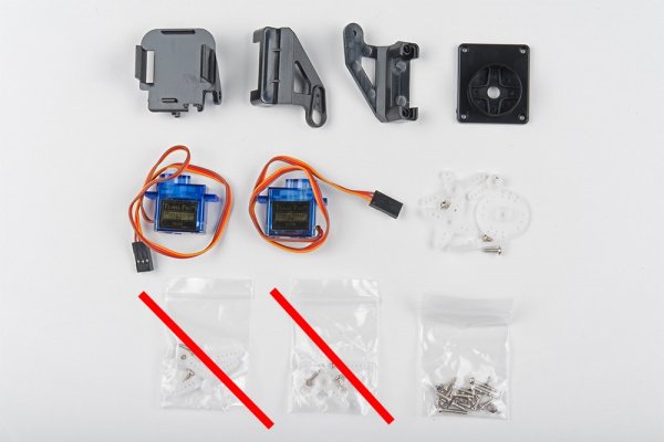
Assembly of the pan-tilt mechanism is fairly straightforward. The trickiest part is making sure the servo motors are centered during assembly.
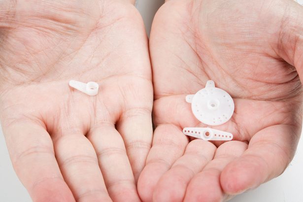
Here’s the family portrait of the stuff that comes in the kit. You won’t be needing the servo horns that come packaged with the servo motors, just the ones that come packaged separately.
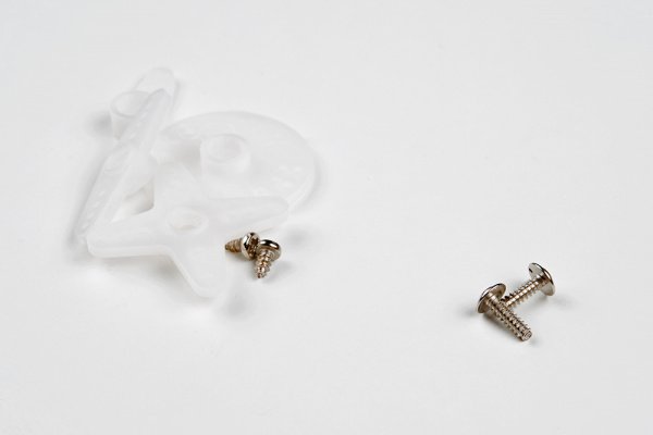
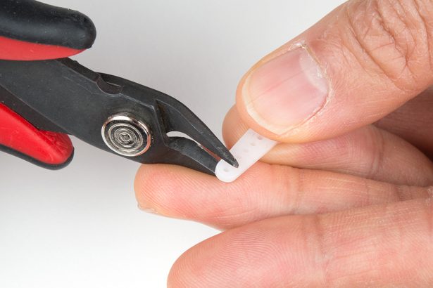
Start by identifying the servo horn with two long arms and two short arms. You’ll need to clip off the long arms, as shown below.

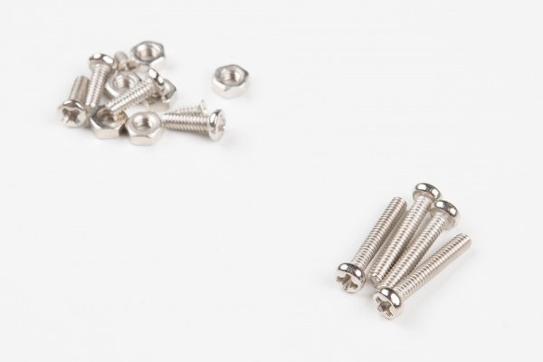
Identify the smallest screws in the baggie of screws that came with the kit. These will be used to affix this horn to the base of the pan-tilt mechanism.
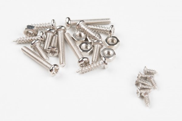
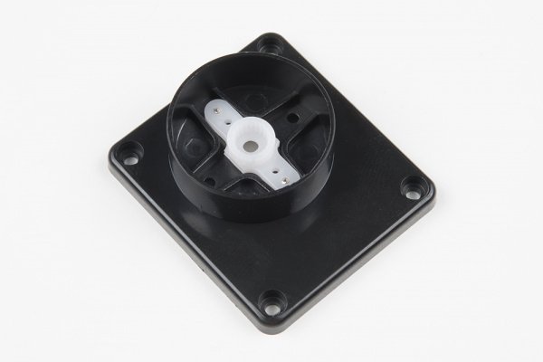
Place the horn in the base as shown, then screw it down by inserting the screws from the bottom and threading them into the horn. Note that there will be extra screws, even beyond the ones to be used later. This is generally true of all the screws in this set.
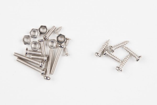
Next, identify the larger self-tapping screws. These will be used for assembling the next part of the mechanism.
Find the two pieces pictured below that will sandwich the first servo. Note the orientation of the servo in these pieces.
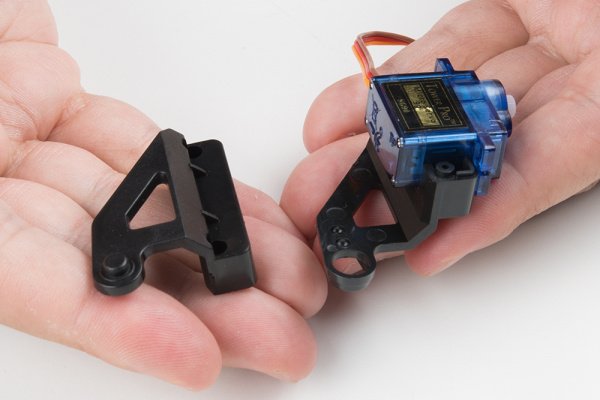
Here’s the sandwiched servo. Again, note the orientation for proper assembly.
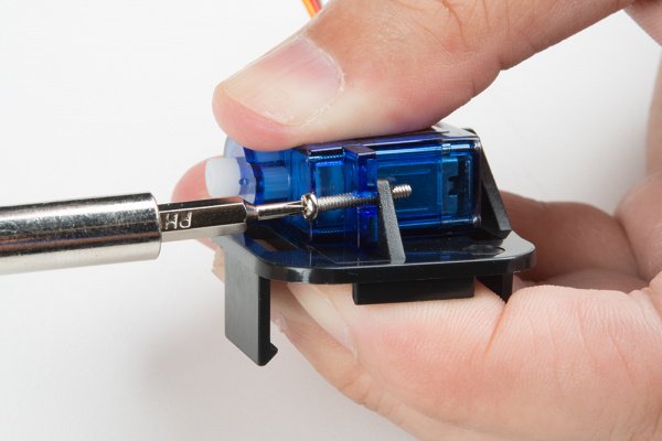
Here, you can see where the screws identified a couple of steps ago fit into our servo sandwich. Tighten them down, but not too much.
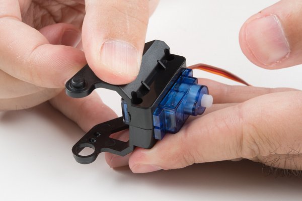
Now fit the shaft of the servo into the fitting on the horn that you previously installed into the base. This is the point where you need to make sure that the shaft is roughly centered in order for the entire assembly to work properly. I do this by turning the shaft all the way to one extreme, then turning it 90 degrees back in the other direction. Then, I remove the base and line it up with the body of the servo motor.
Find the two longer screws that came with the horn kit in the set. There will likely be only two of these, and you need both, so don’t lose one!
You’ll now need the single arm servo horn with 5 holes, as shown in the image below on the left. If the single arm servo with 5 holes was not included in the kit, you will need to modify one of the servo horn with 6 holes that was packaged separately. Shorten the horn by clipping off one hole as shown in the image below on the right and checking to see if it fits the mold on the tilt bracket. Be careful when clipping and make sure that you do not clip off too much of the horn.
Install the single arm servo horn as shown below. You’ll need two of the small self-tapping screws from the first step to affix it to the mechanism.
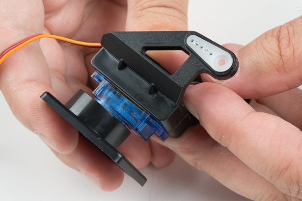
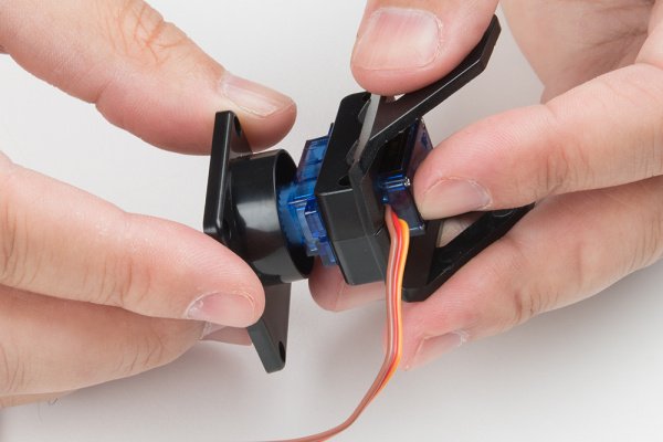
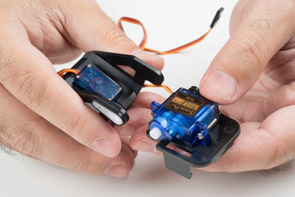
You’ll now need the second servo motor and the last piece of the mechanism. The image below shows the relative orientation of these two pieces.
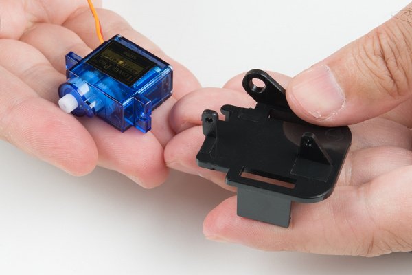
Here’s a picture of the two pieces assembled to one another.
Now, find the longest machine screws in the baggie, as shown below. Once again, you’ll find that there are more of these than you need.
Thread these screws through the stand off wings on the servo motor and into the last piece of the mechanism. You can use nuts for these if you like, but I’ve found it to be unnecessary as they thread into the mechanism quite snugly without the nut.
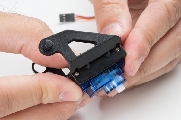
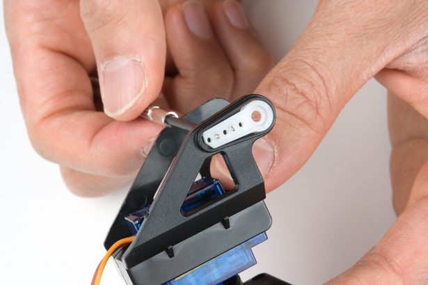
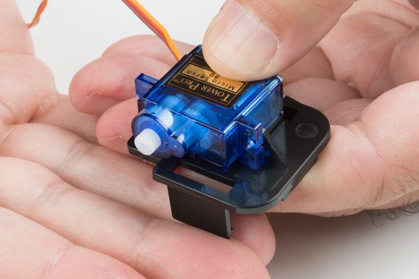
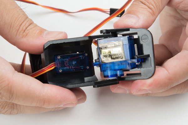
Now connect the two major pieces of the assembly together. The image below shows the orientation of these two parts.
You may need to assemble and disassemble these two parts a couple of times to find the right rotational position of the servo motor so that the tilting portion has its full range of motion. Here’s an image of the two bits put together.
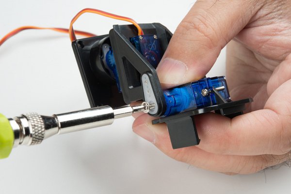
Take the final screw that you identified above as a horn attaching screw and use it to secure the horn to the servo motor.
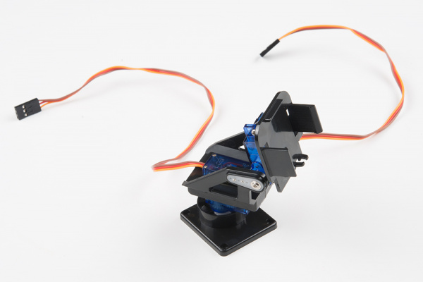
Congratulations, you’ve finished assembly of the pan-tilt mechanism!
Solder the Headers onto the Pi Zero W and Pi Servo Hat
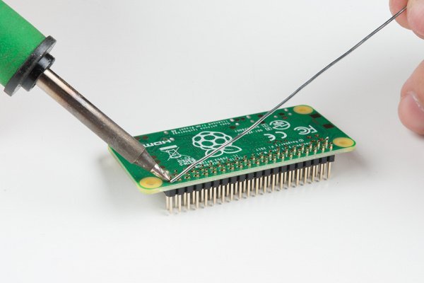
We suggest soldering the male headers onto the Pi Zero W.
My favorite trick for this type of situation is to solder down one pin, then melt the solder on that pin with the iron held in my right hand and use my left hand to adjust the header until it sits flat as shown below. Make sure that you are soldering with the header’s shorter side and the longer pins are on the component side. After tacking down one pin, finish soldering all the pins down to the Pi Zero W.
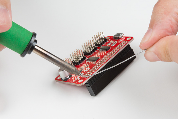
Repeat the steps with the female header and the Pi Servo Hat.
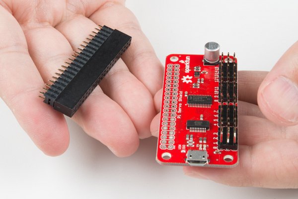
Make sure to insert the short pins from the bottom of the board and add solder to the component side so that the Pi Servo Hat stacks on top of the Pi Zero W’s male header pins. You will also need to make sure that the header is sitting level before soldering down all the pins.
Affix the Camera Module to the Pan-Tilt Mechanism
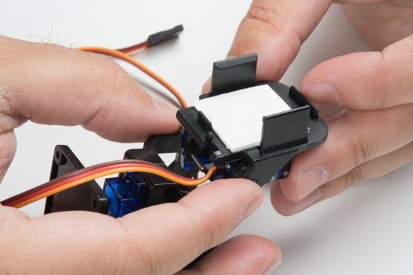
Start by affixing the double stick foam tape to the pan-tilt mechanism as shown in the image below.
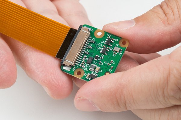
Next, attach the flex cable to the camera module. Take note of the copper “fingers” on the end of the cable. The side with the fingers on it should be facing the camera module circuit board. See the image below.
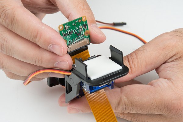
Thread the flex cable through the pan-tilt mechanism as shown below, then press the back of the camera board against the double stick tape to adhere it to the pan-tilt mechanism.
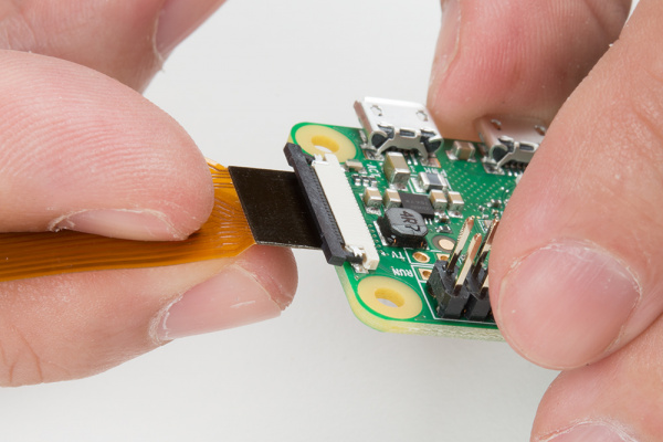
Insert the flex cable from the camera into the Pi Zero W. As was the case with the other end, the side of the cable with the copper fingers should be facing the circuit board. Don’t forget to close the clamping mechanism!
You may now attach the Pi Servo Hat to the header on the Pi Zero W.

Connect the Servo Motors to the Pi Servo Hat
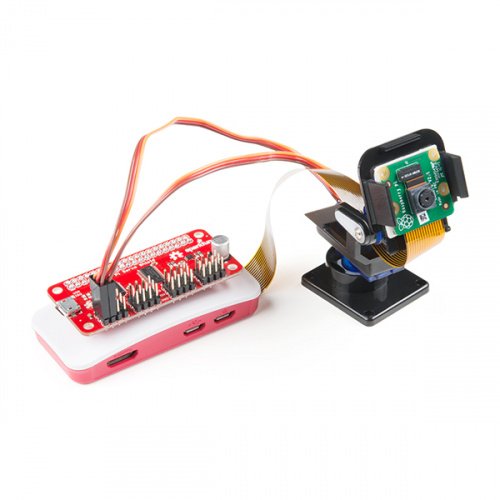
The servo motors need to be connected to channels 0 and 1 on the Pi Servo Hat. Connect the “pan” servo (the one on the bottom) to channel 0 and the “tilt” servo to channel 1.
| Pi Servo Hat (CH 0) | Pan Servo (Bottom of Pan-Tilt Mechanism) | Pi Servo Hat (CH 1) | Tilt Servo |
|---|---|---|---|
| SIG | Control Signal (Orange) | SIG | Control Signal (Orange) |
| POW | Vcc (Red) | POW | Vcc (Red) |
| GND | GND (Brown) | GND | GND (Brown) |
Once connected, your setup should look like the image below.
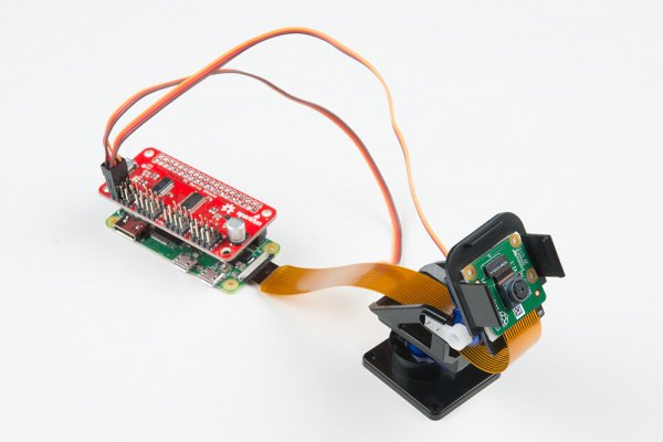
This completes the necessary steps of the hardware assembly!
Read More Info….