
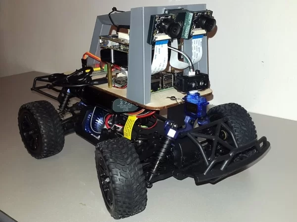
Donkey Car featuring the Ultra96 board, a Raspberry Pi, FPGA accelerated stereo vision, MIPI CSI-2 image acquisition, a LiDAR sensor and AI.
In this project, I will document the build of a Donkey Car enhanced with an advanced vision system using FPGA accelerated stereo vision and LiDAR.
The project consists of the following main components:
- Raspberry Pi 3 featuring 4 x Cortex-A53 cores – runs the AI that drives the car
- Avnet / Xilinx Ultra96 Board – used for video acquisition and processing. The high speed MIPI CSI-2 input of two OV5647 cameras are captured using 2 video pipelines implemented in the programmable logic (FPGA) part of the Xilinx Zynq UltraScale+ MPSoC. The captured images are processed by an OpenCV / xfOpenCV application. Using a hardware accelerated stereo matching algorithm (xfOpenCV StereoBM) is applied on the input images and the depth of the scene is computed in real-time
- Donkey Car – an RC car used for PoC
- 2 x OV5647 5 MegaPixel NoIR Camera
- TFMini LiDAR Sensor
PART 1: Getting Started
1. Getting Started with the Donkey Car
The build of a Donkey Car is pretty well documented.
We can start with hardware part:
- First from our RC car we need to remove the decorative plastic shell and some parts from casing. For RC cars from the kits provided by ARM we can follow this video.
- Then we can continue with the standard build process.
- The result should look like:
The software part consists of:
- Installing software to the SD card.
- Calibrating the PWM values for the throttle and steering.
- Starting the web interface and getting a test drive.
2. Getting Started with the Ultra96
The first thing I tried with the Avnet Ultra96 board, (of sure without reading the getting started guide :D), was to plug in a cable in its micro USB source and see if it powers up. It didn't.
It turned out the Ultra96 must be powered trough the jack connector with 12V 2A power supply. The jack connector is a EIAJ-03 (with 4.75mm outside and 1.7mm inside diameter), which apparently is not a very usual one. As I didn't found such a connector in the house, and (being August) the local electronics store is closed, I decided to “temporally” just solder two wires on the connector pins from the bottom of the board.
After double checking that nothing is shorted out, I was able to power the board from a bench supply (with a 12V and 2.10A current limit):
A powering it up, the board Ultra96 boots in about 30-40 and creates a WiFi network with the name Ultra96_<Mac_Address>.
To access the Ultra96 we need connect this network and access 192.168.2.1 from a browser. An user interface as bellow should be shown. This allows:
- Running examples – for example, controlling the on-board LEDs
- Changing settings – for example, changing the WiFi settings and connecting to my home network:
But, the Ultra96 has more interesting features than this. It has an FPGA!
Vivado Design Suite
To create an FPGA-based project, we need to install the Xilinx Vivado Design Suite. This takes some time, but the result should look like:
Now we can start creating a sample project. I followed this video tutorial, which shows how to create the hardware variant of blinking an LED.
The Xilinx SDK is used to build the Boot image:
The result will be a BOOT.bin file, which should be copied to the SD card. The Ultra96 will boot from the SD card and will program the FPGA with the provided image.
The Blinky LED example should output an about 2-3 Hz square wave to the pin 3 of the low speed header.
As the output is at 1.8V logic level and I didn't have an extension board with level shifter yet, I used my multi-meter and oscilloscope to inspect the signal.
PART 2: Adding a LiDaR Module
3. The TFmini LiDaR Sensor
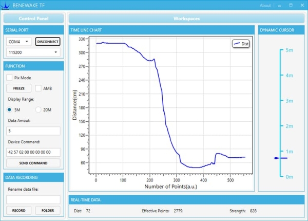
The LiDAR(Light Detection and Ranging) sensor I used is a TFMini from Benewake.
The sensor measures distance by measuring the time-of-flight of a light signal reflected by the measured object. The distance to the object is then calculated using the speed of light.
Benewake has a demo app that can be used to test the sensor:
Also, it is recommended to update the firmware to the latest version (if not already):
4. Building the LiDaR Module
The sensor measures distance in a single direction. This is not so useful, so I decided to build a simple rotating platform to allows measuring distance in 180° degrees. The sensor mounted on a servo motor with allows 180° rotation. In this way the LiDAR sensor is able to measure the distance to the objects surrounding the Donkey Car. Using a collected data a floor map can be built.