Overview
The Raspberry Pi is a small single-board computer (SBC) developed here in the UK, by Raspberry Pi Foundation. It runs various versions of linux on ARM and has a set of I/O pins which you can use to attach external components such as sensors, buttons etc. The Raspberry Pi unfortunately doesn’t have a built in Analog-to-Digital converter so we are unable to use a analog temperature sensor like the TMP36 which works great with the Arduino, the alternative is to use a digital temperature sensor.
Parts
Raspberry Pi
DS18B20 Temperature Sensor
4.8k Ohm Resistor
Prototyping Plate
Pi Cobbler
Half-sized breadboard
Jumper wire pack
Basic Design
Hardware
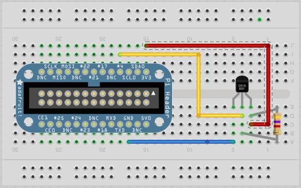
In the basic design all we need is the Raspberry Pi, DS18B20 Temperature Sensor, 4.8k Ohm Resistor, Pi Cobbler, Half-sized breadboard and jumper wires. Everything will be inserted into the breadboard for ease of testing and design.
Wiring Diagram
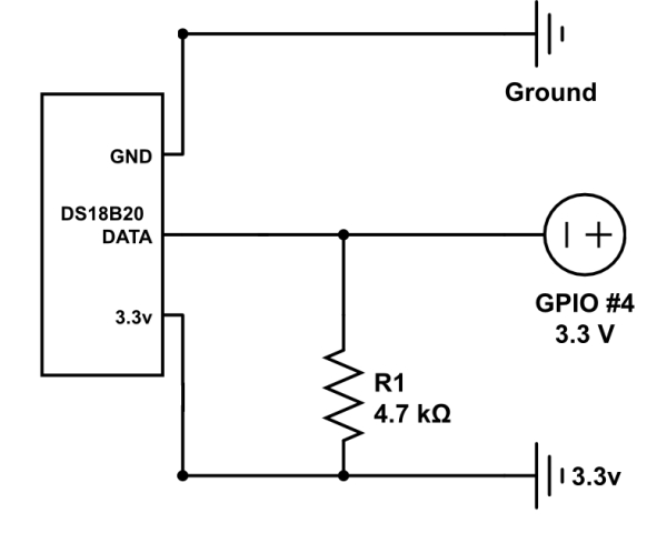
The sensors are fairly unique in that they can be wired in parallel, and as many sensors as desired can be added to the system. The sensors communicate using a single wire serial interface and if you are using Rasbian on the Raspberry Pi it will identify the sensors as connected serial devices. However, the sensor must be wired to pin4 on the GPIO as this is the only pin which (currently) allows communication using the one wire serial protocol.
You can use this diagram from Adafruit’s guide on setting up the DS18B20 temperature sensor to the Raspberry Pi for easier understanding when connecting everything together.
DS18B20
You can purchase the DS18B20 in three forms, a regular transistor looking type component is available, a waterproof version with a long cable attached and a high temperature version.
All three DS18B20 include the special 1-wire serial interface as well as the control logic and temperature sensor itself. It outputs the digital measurements to the Raspberry Pi and depending on your distro, the latest version of Raspbian includes an way to read those messages without an extra work. If you have everything wired together you can test it out over the command line using the below commands.
|
1
2
3
4
5
6
|
sudo modprobe w1–gpio
sudo modprobe w1–therm
cd /sys/bus/w1/devices
ls
cd 28–xxxx (change this to match yours)
cat w1_slave
|
Type the commands you see above into a terminal window. Navigate to the ‘/sys/bus/s1/devices’ directory, In the commands above the ‘cd’ command it set to the directory starting ’28-‘ It may have a different name on you system as its based on the DS18B20’s serial number, so cd to the name of whatever directory is there.
The response will either have YES or NO at the end of the first line. If it is yes, then the temperature will be at the end of the second line, in 1/000 degrees C.
Software
Once the circuit has been put together we now need to write the program to read the temperature data from the sensor, in the basic design the program will read the data every second and display the reading to stdout in terminal.
The software language we are going to use to read the data from the DS18B20 temperature sensor is Python. Add this to a file and save as ‘temp_logger_basic.py’
|
1
2
3
4
5
6
7
8
9
10
11
12
13
14
15
16
17
18
19
20
21
22
23
24
25
26
27
28
29
30
31
32
|
import os
import glob
import time
os.system(‘modprobe w1-gpio')
os.system(‘modprobe w1-therm')
base_dir = ‘/sys/bus/w1/devices/'
device_folder = glob.glob(base_dir + '28*')[0]
device_file = device_folder + ‘/w1_slave'
def read_temp_raw():
f = open(device_file, ‘r')
lines = f.readlines()
f.close()
return lines
def read_temp():
lines = read_temp_raw()
while lines[0].strip()[–3:] != ‘YES':
time.sleep(0.2)
lines = read_temp_raw()
equals_pos = lines[1].find(‘t=')
if equals_pos != –1:
temp_string = lines[1][equals_pos+2:]
temp_c = float(temp_string) / 1000.0
temp_f = temp_c * 9.0 / 5.0 + 32.0
return temp_c, temp_f
while True:
print(read_temp())
time.sleep(1)
|
At the top of the program we include modules that we will use in the script, then it goes on to issuing the ‘modprobe’ commands that are needed to start the interface. The next three lines, find the file from which the data can be read.
There are two functions that handle the reading of the temperature, ‘read_temp_raw’ fetches the two lines of message from the interface. The ‘read_temp’ function returns two values, the temperature in Celsius and the temperature in Fahrenheit every second.
Here is an output of the script.
|
1
2
3
4
5
6
7
8
9
|
sculley@berry:/usr/local/temperature/$ sudo python ./temp_logger_basic.py
(18.875, 65.975)
(18.875, 65.975)
(18.875, 65.975)
(18.875, 65.975)
(18.875, 65.975)
(18.875, 65.975)
(18.875, 65.975)
(18.875, 65.975)
|
The script needs to be run as root, as well you need to use python to call the script as we have not added the Python shebang to the top of the script.
So that’s it, you should have successfully wired up the basic design and wrote the basic script to read the temperature data from the DS18B20 temperature sensor. Now we can move onto the more advanced design.
 Advanced Design
In the advanced design I will show you my design of my temperature logger which I have soldered the components onto a PCB shield which plugs into the Raspberry Pi and is stored inside a small black box to hide everything, the code runs every hour and stores the data to a MySQL database, I use this to display the data in a Google Chart which makes it easier to visualize.
Hardware
For the advanced design we need the same parts as the basic one except the Pi Cobbler (Raspberry Pi, DS18B20 Temperature Sensor, 4.8k Ohm Resistor, Half-sized breadboard and jumper wires) but we also need a PCB, I bought the Raspberry Pi prototyping shield from Adafruit which is great for making semi-permanent designs.
For more detail: Temperature Monitoring on the Raspberry Pi


