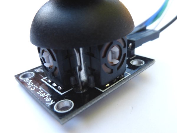
While browsing eBay looking at electronics stuff I found a few interesting items to connect to the Pi. The first item was a small 2-axis analogue joystick. They are similar to the thumb-sticks you would find on a modern games console controller. These modules are cheap and easy to connect to a circuit so I decided to get one. The outputs are analogue so you need a mechanism for the Pi to read these voltages.
In this post I’ll show how you can you use this device with the Pi. Once working this could be used as an input device for all sorts of projects. Perhaps a Python game written using the Pygame module?

In order to measure the X and Y voltages I decided to use an MCP3008 10 bit Analogue to Digital Converter. These devices are cheap, easy to setup and allow 8 analogue inputs to be read by the Pi using it’s SPI interface. In this tutorial we will only need three of its inputs.
See my previous MCP3008 post for details of how I used one to read light levels and temperature.
Breadboard Circuit
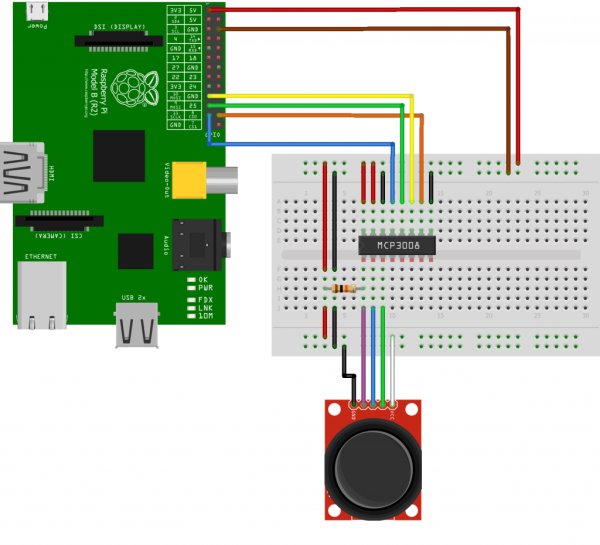
Here is my test circuit. The pin-out of my joystick is slightly different to the Sparkfun symbol I used in this diagram but the wire colour coding matches the photos.
Here is the wiring information for the joystick module :
Joystick          Pi/MCP3008              Wire Colour
--------------    ----------------------  ----------------
GND  (Ground)     Pi GPIO Pin 6 (Ground)  Black
5V   (3.3V)       Pi GPIO Pin 1 (3.3V)    White
SW   (Switch)     MCP3008 Pin 1 (CH0)     Purple
VRx  (X voltage)  MCP3008 Pin 2 (CH1)     Blue
VRy  (Y voltage)  MCP3008 Pin 3 (CH2)     Green
The MCP3008 is wired up just as it was in my previous post :
MCP3008           Pi                      Wire Colour
--------------    ----------------        -----------
Pin 1  (CH0)      -                       Purple
Pin 2  (CH1)      -                       Blue
Pin 3  (CH2)      -                       Green
Pin 9  (DGND)     Pin 6  (Ground)         Black
Pin 10 (CS)       Pin 24 (GPIO8)          Orange
Pin 11 (DIN)      Pin 19 (GPIO10)         Yellow
Pin 12 (DOUT)     Pin 21 (GPIO9)          Green
Pin 13 (CLK)      Pin 23 (GPIO11)         Blue
Pin 14 (AGND)     Pin 6  (Ground)         Black
Pin 15 (VREF)     Pin 1  (3.3V)           Red
Pin 16 (VDD)      Pin 1  (3.3V)           Red

The 10K resistor is used to pull the switch input High (3.3V). When the switch is pressed the input is connected to ground (0V). Without the resistor the input would be in an undefined state when the switch wasn’t being pressed and read random values. Give it a try.
Pi SPI Configuration
In order to use the MCP3008 we need to configure the SPI bus on the Pi first. Rather than repeat the instructions here open the Analogue Sensors On The Raspberry Pi Using An MCP3008 tutorial in a new browser window and complete the sections :
- Enable Hardware SPI
- Install Python SPI Wrapper
For more detail: Using A Joystick On The Raspberry Pi Using An MCP3008

