
RGB LEDs consist of a red, a green and a blue LED conveniently encapsulated in one package. Theoretically one such should be able to produce any colour of the rainbow, but I have restricted my project – for reasons explained later – to just red, green, blue, cyan magenta, yellow and white.
The project uses my 5 in 16 out Raspberry Pi interface. The output GPIO lines are 2, 3, 4, 17,27,22,10,9,11,7,8,25,24,23,18 and 15. Any interface providing these lines should be a suitable substitute for my little effort.
 The circuit
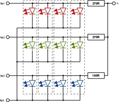
I only managed to buy a packet of 50 common cathode LEDs. As the output logic of my interface board is of the current sinking type, I had to use a little trick to switch 16 LEDs. The circuit diagram of four of them is below, to demonstrate the principle.
The diagram shows four LEDs each one containing a red, green and blue semi conductor in one row of the arrangement. The final circuit uses four rows like the one above. Notice that the LEDs are switched in parallel – which is usually not a very good idea but it worked out very well indeed in this case. The anodes of the LEDs are connected to current limiting resistor. The anodes are also connected to three of the GPIO ports. To turn an LEDs ON, Ports 1 to n3 have to go high. This allows current to flow through the LEDs. To turn them OFF, Port 1 to 3 go low. Current will now flow from the supply through the current limiting resistors into the ports and because the LEDs need a turn-on voltage of more than a volt, they will be OFF.
This means of course that the circuit will use power in both the ON and the OFF state. To prevent this, the cathodes of each of the four rows of LEDs are connected to another GPIO port. When Port 2 is low, its row of LEDs in ON, when it goes high, no current will be consumed and all four LEDs are OFF.
This roundabout procedure was forced on me by the fact that I couldn't buy common anode LEDs.
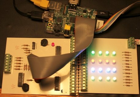
 he pcb on the left might make things a bit clearer. I did not feel like drawing a complete circuit diagram with all those LEDs (48 all told!). The LEDs of the top row are connected thus: four red LEDs to GPIO port 15, four green LEDs to GPIO port 18, four blue LEDs to GPIO port 23. The cathodes are connected to GPIO port 2. It is clear that one row uses four GPIO ports hence all four rows use up all the ports available.
If you find this confusing let me assure you that it confused me too, at first.
Notice also that the connections to the LEDs are very close together. In fact they are on a 0.1 inch grid and you need to have a steady hand with a soldering iron to solder those tightly packed joints. One of the reasons why I switched the LEDs in parallel – it cut out a great many resistor connections!
The program
|
Below is a link to an archive containing the demo-program and the draw file of the pcb. Here is a link to a video of the project:
|
10 REM RGB_LED_Demo 20 REM Play with 16 multi coloured LEDs 30 REM Jochen Lueg 40 REM January 2013 50 REM http://roevalley.com 60 70 ON ERROR PROCerror:STOP 80 90 PROCinit 100 110 120 REM Red, green and blue 130 REM Flash red 140 T%=40 150 160 REM Flash red 170 PROCrgb_flash(0,1,1,R1%,G1%,B1%,S1%,T%) 180 190 REM shift red 200 PROCturn_on(0,1,1,R2%,G2%,B2%,S2%) 210 REM Flash green 220 PROCrgb_flash(1,0,1,R1%,G1%,B1%,S1%,T%) 230 240 REM Shift red 250 PROCturn_on(0,1,1,R3%,G3%,B3%,S3%) 260 REM Shift green 270 PROCturn_on(1,0,1,R2%,G2%,B2%,S2%) 280 REM Flash blue 290 PROCrgb_flash(1,1,0,R1%,G1%,B1%,S1%,T%) 300 REPEAT 310 REM Shift red 320 PROCturn_on(0,1,1,R4%,G4%,B4%,S4%) 330 REM Shift green 340 PROCturn_on(1,0,1,R3%,G3%,B3%,S3%) 350 REM Shift blue 360 PROCturn_on(1,1,0,R2%,G2%,B2%,S2%) 370 REM Flash cyan 380 PROCrgb_flash(1,0,0,R1%,G1%,B1%,S1%,T%) 390 400 REM Shift green 410 PROCturn_on(1,0,1,R4%,G4%,B4%,S4%) 420 REM Shift blue 430 PROCturn_on(1,1,0,R3%,G3%,B3%,S3%) 440 REM Shift cyan 450 PROCturn_on(1,0,0,R2%,G2%,B2%,S2%) 460 REM Flash magenta 470 PROCrgb_flash(0,1,0,R1%,G1%,B1%,S1%,T%) 480 490 REM Shift blue 500 PROCturn_on(1,1,0,R4%,G4%,B4%,S4%) 510 REM Shift cyan 520 PROCturn_on(1,0,0,R3%,G3%,B3%,S3%) 530 REM Shift magenta 540 PROCturn_on(0,1,0,R2%,G2%,B2%,S2%) 550 REM flash yellow 560 PROCrgb_flash(0,0,1,R1%,G1%,B1%,S1%,T%) 570 580 REM Shift cyan 590 PROCturn_on(1,0,0,R4%,G4%,B4%,S4%) 600 REM Shift magenta 610 PROCturn_on(0,1,0,R3%,G3%,B3%,S3%) 620 REM Shift yellow 630 PROCturn_on(0,0,1,R2%,G2%,B2%,S2%) 640 REM flash white 650 PROCrgb_flash(0,0,0,R1%,G1%,B1%,S1%,T%) 660 670 REM Shift magenta 680 PROCturn_on(0,1,0,R4%,G4%,B4%,S4%) 690 REM Shift yellow 700 PROCturn_on(0,0,1,R3%,G3%,B3%,S3%) 710 REM Shift white 720 PROCturn_on(0,0,0,R2%,G2%,B2%,S2%) 730 REM Flash red 740 PROCrgb_flash(0,1,1,R1%,G1%,B1%,S1%,T%) 750 760 REM Shift yellow 770 PROCturn_on(0,0,1,R4%,G4%,B4%,S4%) 780 REM Shift white 790 PROCturn_on(0,0,0,R3%,G3%,B3%,S3%) 800 REM Shift red 810 PROCturn_on(0,1,1,R2%,G2%,B2%,S2%) 820 REM Flah green 830 PROCrgb_flash(1,0,1,R1%,G1%,B1%,S1%,T%) 840 850 REM Shift white 860 PROCturn_on(0,0,0,R4%,G4%,B4%,S4%) 870 REM Shift red 880 PROCturn_on(0,1,1,R3%,G3%,B3%,S3%) 890 REM Shift green 900 PROCturn_on(1,0,1,R2%,G2%,B2%,S2%) 910 REM Flash blue 920 PROCrgb_flash(1,1,0,R1%,G1%,B1%,S1%,T%) 930 940 950 UNTIL FALSE 960 *QUIT 970 STOP 980 990 DEFPROCrandom 1000 1010 FOR J%=0 TO 15 1020 SYS"GPIO_WriteData",Port%(J%),0 1030 NEXT 1040 1050 ENDPROC 1060 1070 1080 1090 DEFPROCrgb_flash(r%,g%,b%,R%,G%,B%,S%,t%) 1100 SYS"GPIO_WriteData",R%,r% 1110 SYS"GPIO_WriteData",G%,g% 1120 SYS"GPIO_WriteData",B%,b% 1130 SYS"GPIO_WriteData",S%,1 1140 Key$=INKEY$(1) 1150 IF Key$="1" T%=10 1160 IF Key$="2" T%=20 1170 IF Key$="3" T%=30 1180 IF Key$="4" T%=40 1190 IF Key$="5" T%=50 1200 IF Key$="6" T%=60 1210 IF Key$="7" T%=70 1220 IF Key$="8" T%=80 1230 IF Key$="Q" OR Key$="q" PROCstop:END 1240 1250 TIME=0:REPEAT UNTIL TIME>T% 1260 ENDPROC 1270 1280 1290 DEFPROCturn_on(r%,g%,b%,R%,G%,B%,S%) 1300 SYS"GPIO_WriteData",R%,r% 1310 SYS"GPIO_WriteData",G%,g% 1320 SYS"GPIO_WriteData",B%,b% 1330 SYS"GPIO_WriteData",S%,1 1340 ENDPROC 1350 1360 1370 DEFPROCstop 1390 FOR J%=0 TO 15 1400 SYS"GPIO_WriteData",Port%(J%),0 1410 NEXT 1440 ENDPROC 1450 1460 1470 DEFPROCerror 1520 PROCstop 1530 PRINT REPORT$;" at line ";ERL:END 1540 ENDPROC 1550 1560 1570 DEFPROCinit 1580 OSCLI"RMEnsure GPIO 0.00 RMLoad GPIO" 1590 OSCLI"RMensure GPIO 0.40 ERROR Please install the GPIO module" 1600 1610 SYS"GPIO_EnableI2C",0 1620 SYS"GPIO_ExpAsGPIO",2 1630 1640 DIM Port%(15) 1650 REM ISSUE 2 Interface board 5x16 1660 Port%()=2,3,4,17,27,22,10,9,11,7,8,25,24,23,18,15 1670 REM Set up the otput lines 1680 FOR J%=0 TO 15 1690 SYS"GPIO_WriteMode",Port%(J%),1 1700 NEXT 1710 1720 R1%=15:G1%=18:B1%=23:S1%=2 1730 R2%=24:G2%=25:B2%=8:S2%=3 1740 R3%=7:G3%=11:B3%=9:S3%=4 1750 R4%=10:G4%=22:B4%=27:S4%=17 1760 ENDPROC |