
This instructable should help you set up a DIY home security + automation system that uses 433Mhz door/window sensors, 433 MHz PIR motion sensors and webcams to monitor your home and 433MHz outlets to control lights etc.
The original project was completed in phases and published on my personal blog at http://tkmaker.blogspot.com/2013/11/raspberry-pi-h…. This instructable is aimed at putting all that information together in one place.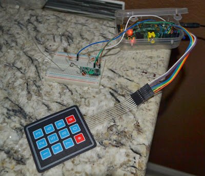
Step 1: Hardware Component List
- Raspberry Pi
- 433 MHz Transmitter/Receiver $2.77- http://www.ebay.com/itm/121117930415?ssPageName=ST…
- Note that I only used the transmitters here. The receivers were of poor quality and the superheterodyne receiver below was the one I landed up using finally. You could only purchase the transmitters to reduce the cost.
- 433 MHz Super Heterodyne Receiver $5.99 – http://www.ebay.com/itm/280936648330?ssPageName=ST…
- 4×3 Membrane Keypad $3.95 – http://www.adafruit.com/products/419
- 433Mhz Piezo Siren $17.91 – http://www.ebay.com/itm/433MHz-Wireless-Strobe-Li…
- The hardware below is what I used for this project – You can always get more of each based on your requirements:
- 4x 433 MHz door/window sensors $12.99 – http://www.ebay.com/itm/190940498983?ssPageName=ST…
- 2x 433 MHz PIR Motion sensors $17.16 – http://www.ebay.com/itm/433Mhz-Wireless-PIR-Motion…
- 3x 433 MHz Remote controlled wall outlets $25 – http://www.dbtechusa.com/#!remote-control-outlet/c…
The total hardware cost was approximately $85 (minus the Raspberry Pi)
Step 2: Hardware Setup
1. To increase the range of the transmitter and receiver, solder a 17cm single core wire to the ANT (antenna) connection on the transmitter and receiver.
2. Connect the DATA output of the transmitter to GPIO 17 of the Raspberry Pi (rev B in my case)Connect the DATA output of the transmitter to GPIO 17 of the Raspberry Pi (rev B in my case)
3. Connect the DATA pin input of the superheterodyne receiver to GPIO 21
4. Connect the VCC/GND pins of the 433MHz Rx/Tx to the Raspberry Pi 5V/GND lines
5. The 4×3 membrane keypad is connected as follows:
• Pin 7 on the keypad is ROW 0- GPIO 18
• Pin 6 on the keypad is ROW 1- GPIO 23
• Pin 5 on the keypad is ROW 2- GPIO 24
• Pin 4 on the keypad is ROW 3- GPIO 25
• Pin 3 on the keypad is COL 0 – GPIO 4
• Pin 2 on the keypad is COL 1 – GPIO 22
• Pin 1 on the keypad is COL 2 – GPIO 10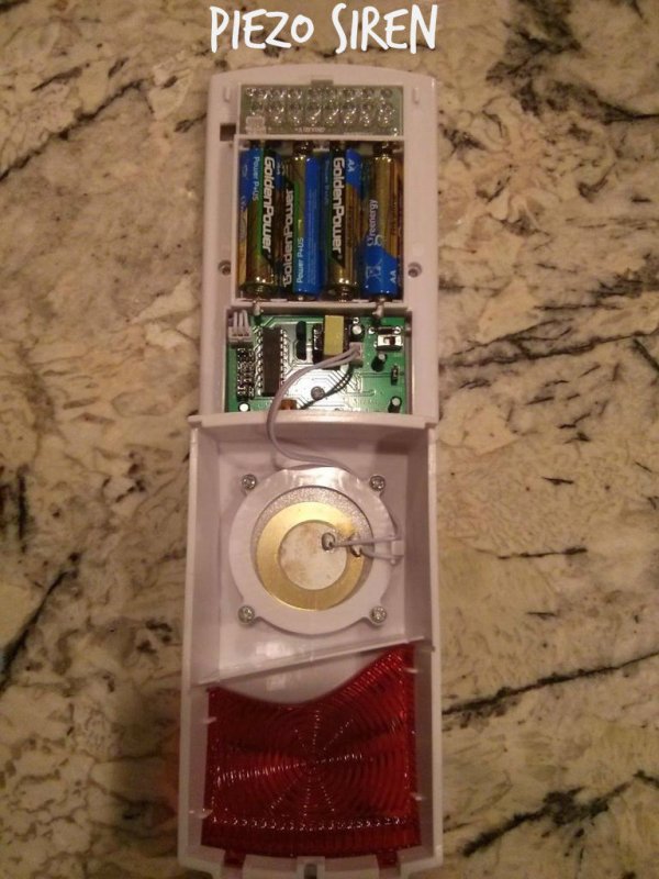
Step 3: Install prerequisite software + source code
1. Install WebIOPi from here: http://www.themagpi.com/issue/issue-9/article/web…
2. Install motion for webcam motion detection: sudo apt-get install motion
• For details on how to setup motion, take a look at my post here: http://tkmaker.blogspot.com/2013/11/raspberry-pi-…
3. I found this article on using 433MHz Tx-Rx modules with the raspberry pi. Follow the instructions here to install the 433Utils package. http://ninjablocks.com/blogs/how-to/7506204-addin…
• Run RFSniffer and trigger all the 433MHz door/window/PIR motion sensors that you want to use and note down the received code. This will be used to trigger the alarm in your system.
4. Clone my git repo for the source code from here: https://github.com/tkmaker/RaspberryPiHomeAlarm to any directory
For more detail: DIY Home Security + Automation using a Raspberry Pi