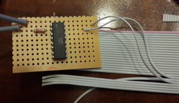
The first step of building the Raspberry Pi-powered speaking doorbell is building a simple input circuit. The purpose of the input circuit is to protect the Pi from damage by electrically isolating the doorbell and its power supply from the Raspberry Pi itself.

On the left are the 2 single-core cables that are connected to my doorbell and its 12V power supply. The + (anode) of the 12V power supply is wired to my doorbell button which in turn is connected to the input circuit (top left cable). The bottom-left cable on the input circuit is then connected to the – (cathode) of the power supply.
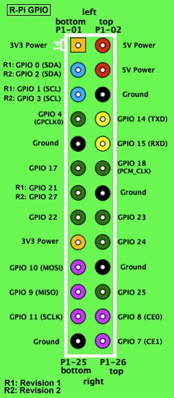
On the right-hand side, you’ll notice a ribbon cable. I have a model B Raspberry Pi, which has a 26 pin P1 header. I bought a 26pin IDC crimp connector and some ribbon cable, which fits perfectly on the P1 header.

For more detail: The Raspberry Pi Powered Speaking Doorbell – Part 1: The Input Circuit

